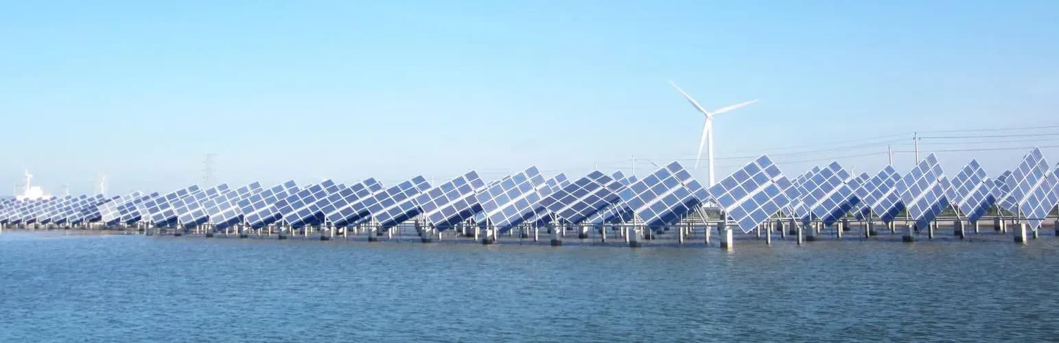
Photovoltaic plants built on water collapse the corrosion safety margin that mainland EPCs rely on. Salt spray, full-time humidity, UV at sea-surface intensity, wave-induced vibration, and biological loading from fish and bird waste all act on the same steel and aluminum that worked perfectly inland. Conventional hot-dip galvanized mounts and anodized aluminum frames give up 30 to 50 percent of their nameplate life in this environment. Pultruded fiber reinforced polymer (FRP) profiles are corrosion-immune by chemistry rather than by coating, and they cover both the mounting structure and the module frame.
Three water-side scenarios, one set of failure drivers
Offshore floating, tidal-flat, and fishery-PV sites differ in elevation and in what sits below the array, whether that is open sea, intertidal mud, or aquaculture ponds. The dominant corrosion drivers converge on the same short list.
| Scenario | Service condition | Dominant degradation drivers |
|---|---|---|
| Offshore / floating PV | Permanent immersion, tidal cycling, swell | Salt spray, chloride attack, anodic current, biofouling |
| Tidal-flat PV | Alternating wet and dry, sediment scour | High humidity with chloride, sand abrasion, wet-dry cycles |
| Wind-solar-fishery hybrid | Pond surface, freshwater-saline mix | Ammonia and H₂S from biology, UV, fish and bird waste, wind vibration |
In corrosion terms the three sites converge on chloride plus moisture plus UV plus vibration plus localised acid or alkaline attack. That combination is the worst environment any 25-year solar warranty has to survive.
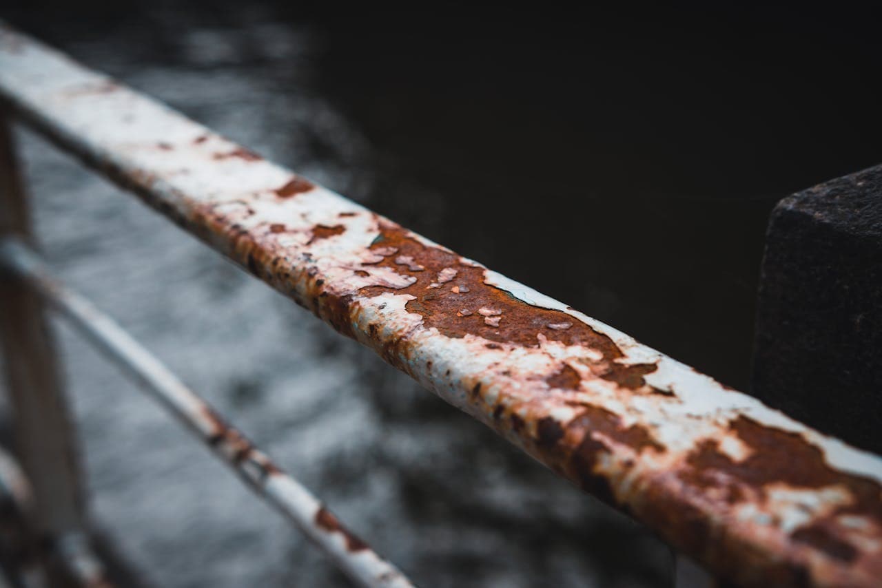
Why galvanized steel and aluminum fall short on water
Hot-dip galvanized steel mounts corrode at the C5-M coastal grade at roughly 50 to 200 µm of zinc loss per year. A typical 60 to 85 µm zinc layer is consumed in five to eight years, and the red rust that follows stains module glass, drops shading patches across cells, and forces unplanned coating renewal far from shore.
Aluminum module frames and mounts pit aggressively in salt environments. When the same array bolts stainless fasteners and copper grounding cables to aluminum, a galvanic couple forms and the aluminum becomes the sacrificial anode. Designs scoped for a five-year inspection cycle are usually re-scoped to two or three years in service, eating the IRR projected at financial close.
Stainless steel is often proposed as the fix. 304 is open to stress-corrosion cracking under chloride loading, and 316L pushes the bill of materials past the budget for most utility-scale projects on the water. Where a coastal or floating PV plant inherits a mainland mounting specification unchanged, the operations and maintenance line in its LCOE is routinely understated by more than 30 percent.
How pultruded FRP carries the structure
Glass-fiber-reinforced thermoset polymer profiles produced by pultrusion meet the structural demands of marine-class PV plants on intrinsic chemistry rather than on a coating. A pultruded E-glass plus vinyl ester or polyurethane composite does not react with Cl⁻ or SO₄²⁻. There is no sacrificial coating to renew, no cathodic protection circuit to power, and no zinc-loss rate to budget against.
Specific strength is the second argument. Pultruded FRP delivers longitudinal tensile strength on the order of 600 MPa at a density of about 1.9 g/cm³, roughly a quarter of carbon steel. The reduced dead load relaxes the design of pontoons, piles, and lifting equipment.
Dielectric performance is the third. Volume resistivity above 10¹² Ω·cm means FRP profiles can run alongside HV cabling without inducing stray-current corrosion in adjacent steel, and they remove an entire class of safety-case complications around DC-side grounding faults.
The fourth is fatigue behavior under combined wind and wave loading. With no metallic crack-initiation sites, FRP cross-sections retain more than 90 percent of their static strength after 10⁷ load cycles. Aluminum and high-strength steel cannot match that margin in chloride service.
F1 Composite produces the full set of structural members typical of an offshore or fishery PV plant: I-beams, channels, angles, square tube, round tube, and custom hat sections for purlins, rafters, struts, posts, walkways, and cable trays.
How pultruded FRP replaces the aluminum module frame
The module frame is the second weather-exposed structure on every panel, and historically it has been an aluminum extrusion. On water, three properties of pultruded FRP make the substitution straightforward.
FRP frames have a longitudinal coefficient of thermal expansion near 6 × 10⁻⁶/°C, compared with about 23 × 10⁻⁶/°C for aluminum. The narrower mismatch with the glass reduces silicone seal cycling on bifacial double-glass modules and extends the rated edge-seal life.
Replacing an aluminum frame with a pultruded FRP frame typically removes 0.6 to 1.2 kg from a 630 W or 700 W module, which makes two-person installation on floating walkways and pond catwalks substantially easier.
Accelerated weathering per ASTM G154 shows color shift ΔE below 3 after 3000 hours of UV-A exposure on a properly stabilised polyurethane or polyester pultruded frame, with no chalking on the public-facing surface. Aluminum anodization cannot match that in fishery environments rich in nitrogen and sulphur volatiles.
F1 Composite manufactures pultruded FRP module frame profiles for N-type TOPCon, HJT, double-glass bifacial, and BIPV module formats, with click-fit, structural-adhesive, and gasket-sealed assembly options engineered around the cell-string layout.
LCOE over 25 years
The purchase-price comparison between FRP and galvanized steel is the wrong place to anchor the decision. The lifecycle comparison reads differently.
| Dimension | Galvanised steel or anodized aluminum | Pultruded FRP |
|---|---|---|
| Real coastal service life | 8 to 12 years | 25 years, maintenance-free |
| Coating renewal cycle | 5 to 8 years | None required |
| Galvanic and stray-current corrosion | High risk | Not a failure mode |
| Mass at equivalent section | Reference | Roughly one quarter of steel, 70 percent of aluminum |
| Site cutting and drilling | Cold-work then re-protect | Cold-work, no re-protection required |
| Maintenance opex over 25 years | Adds 30 percent plus to LCOE | Removed from the opex line |
This is the same conclusion drawn in the broader [FRP vs steel structural comparison](/resources/blog/frp-vs-steel-structural-profiles). On water, the more aggressive the environment and the more expensive the maintenance access, the harder the FRP case is to refuse.
Substitution map for a hybrid PV plant
Reading the cover image as a system, the corrosion-exposed surfaces of an offshore or fishery PV plant split into four substitution zones.
Wind turbine support area. Wind and wave coupling drives vibration into the support frame. Pultruded FRP main beams and braces remove metallic fatigue-crack initiation from the load path.
PV array above the water surface. The bifacial modules and their mounts sit in the salt-spray zone year-round. Pultruded FRP purlins, rafters, and module frames handle the exposure on chemistry alone.
Piles entering the water. The intertidal band is the highest-corrosion-rate part of any steel pile. Pultruded FRP posts or FRP-jacketed concrete piles take that band out of the failure path.
High-voltage transmission run. Pultruded FRP cross-arms replace porcelain insulators and steel cross-arms in one step. The dielectric performance is intrinsic to the material.
Replacing the metallic exposure surface across the plant turns the 25-year warranty from a financial-model assumption into a material-level fact.
For a project-specific FRP solar mounting specification, full pultruded section drawings, or a comparative LCOE model, contact F1 Composite engineering through [the contact form](/contact) or browse the [FRP solar mounting application page](/applications/frp-solar-mounting-profiles).