Skip to content
Industry· Automotive & rail

FRP Profiles for Automotive, Bus & Rail Components

Explore custom pultruded FRP profiles for selected passenger-car reinforcements, EV battery-pack details, bus and coach bodies, commercial vehicles and rail interiors. Long, constant-section parts are evaluated against the vehicle program's loads, joints, environment and approval requirements; a candidate location is not a qualified replacement part.

FIG. 1 Automotive & rail
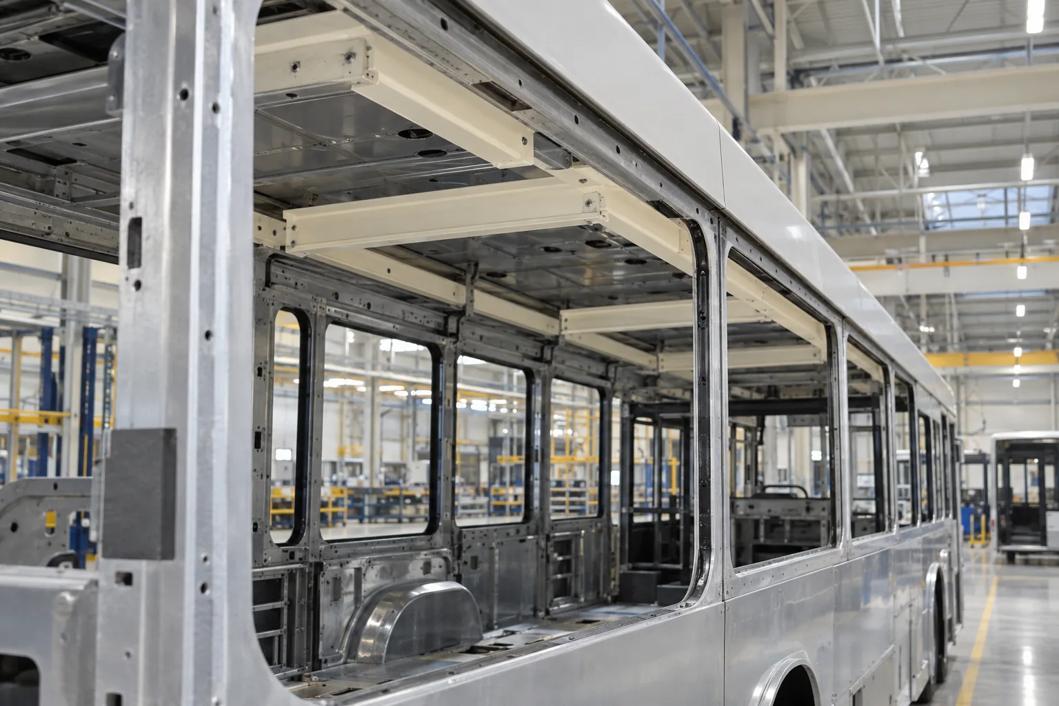
Bus body showing candidate roof and ceiling support-profile locations
Candidate roof and ceiling rail locations in a bus body; final components require vehicle-maker design and approval.

Where FRP is used, area by area

Start with the component's function and installation interface. These are candidate locations for long, constant-section FRP parts, each with its own acceptance basis.
AreaConditionsTypical FRP partsWhat to check
Bus and coach bodiesLong body details exposed to vibration, passenger use, weather and cleaningSide-skirt edges, luggage-rack rails, ceiling supports, duct and hatch framingFixture and access loads, joint fatigue, finish and applicable bus fire rules
Passenger carsMass and packaging constraints around crash and occupant load pathsCandidate bumper, sill, seat-crossmember or seat-frame sectionsOEM crash and restraint load cases, joint performance and production variation
EV battery packsUnderbody impact, moisture, temperature cycling and high-voltage interfacesCandidate pack cross rails, end members, cell restraint bars and cover-edge profilesPack-level crush, fire and electrical requirements, sealing and metallic inserts
Trucks and refrigerated bodiesCargo impact, road salt, washdown and thermal bridges in insulated wallsWall sideposts, liner fixing rails, roof or floor edge profilesFastener loads, wall-level heat transfer, sealing and repair access
Rail vehiclesVibration, cleaning and location-specific fire, smoke and toxicity requirementsRoof-edge, interior support, luggage-rack and cable-cover profilesEN 45545-2 or local requirement set, tested configuration and joint durability
Specialty vehiclesEquipment compartments exposed to salt, water, detergents and repeated accessEquipment-door frames, panel edging and secondary mounting railsEquipment mass, attachment cycles, exposure and service replacement

Vehicle component opportunities 6 applications

Pultrusion is suited to continuous, repeatable profiles with a constant cross-section. Straight lengths are the usual starting point; controlled curvature needs a separate manufacturing review. This application review covers possible positions from passenger-car beams and battery-pack rails to bus, truck and rail details. Each candidate needs its own section, laminate, joint design and vehicle-program acceptance basis.

01 · Bus & coach

Long body details around the bus structure

Bus and coach bodies contain repeatable edge, support and enclosure sections where a custom pultruded profile can be studied alongside the metal body structure.

Candidates include side-skirt and wheel-arch edge profiles, luggage-rack rails, ceiling and interior-panel supports, HVAC duct edges, and luggage-door or service-hatch surrounds. The section may combine a mounting land, edge return and finished face. A complete bus frame, roof shell or crash structure is a different design and approval scope.

Separate exterior and interior duties. A skirt edge sees road debris, water and repair activity; a rack or ceiling support carries fixture loads and repeated vibration; a hatch frame adds hinge and latch cycles. Define deflection, impact and attachment loads before sizing the section. The OEM also identifies any applicable material-burning requirement for the bus class and location.

Components to evaluate

  • Side-skirt, wheel-arch and roof-edge details
  • Luggage-rack, ceiling and interior-panel support rails
  • Luggage-door, service-hatch and HVAC duct framing

Design and approval checks

  • Fixture loads, door cycles, vibration and allowable deflection
  • Metal-interface bearing, bond or bolt detail and thermal movement
  • Stone impact, cleanability, finish repair and applicable fire rules
02 · Passenger cars

Treat reinforcement beams as complete vehicle systems

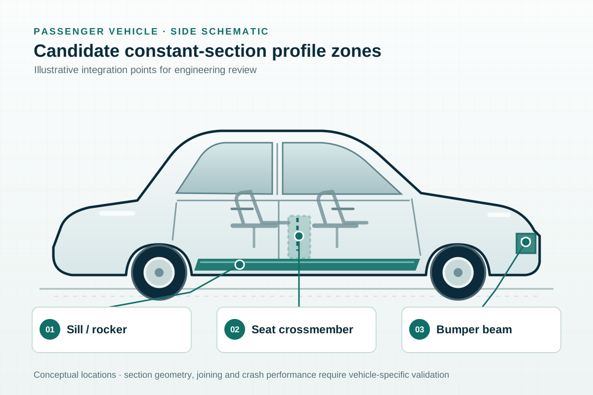
A bumper reinforcement, side sill or seat crossmember may have a long, fairly constant section, making pultrusion a process candidate. Geometry alone does not establish crash or occupant-safety suitability.

A bumper beam works with crush cans, mounts and surrounding body structure. A side sill contributes to side-impact and underbody load paths. For either candidate, the OEM must set target force-displacement behavior, intrusion limits, failure mode, attachment loads and repair rules, then validate the installed system through its vehicle program.

Seat crossmembers and selected backrest rails add occupant and restraint loads, repeated adjustment or vibration, and local fastening demands. Inserts, drilled holes and bond lines often govern the usable strength more than a coupon result; review them with the proposed laminate and production tolerances.

FIG. 2 Passenger cars
Technical illustration marking candidate bumper, side-sill and seat reinforcement locations on a passenger car; conceptual, not an F1-supplied vehicle

Components to evaluate

  • Front or rear bumper reinforcement profiles
  • Side-sill and door-opening reinforcement sections
  • Seat crossmember or backrest-rail candidates

OEM study inputs

  • Crash pulse, intrusion and energy absorption in the assembled load path
  • Seat and restraint loads, fatigue and misuse cases where applicable
  • Bonded or bolted joints, inserts, tolerances and repair method

03 · EV battery packs

Define the duty of each battery-pack member

EV packs contain several long parts with different jobs. A cross rail or end member carries mechanical loads; a cell restraint bar controls local clamping; a cover or underbody edge profile supports a joint or seal.

Treat these as separate specifications. Cross members require pack-level bending, crush and attachment checks. Cell restraints need controlled clamp load and long-term dimensional stability. Cover-edge or floor-shield edging must fit the seal, drainage and service-opening design. A pultruded profile should be compared with the complete installed alternative, including metal inserts and fasteners.

Glass FRP can be considered where an insulating section is useful, but laminate data alone do not qualify a high-voltage boundary. Moisture, coolant, contamination, metallic hardware and temperature cycling affect the assembly. The battery-system team defines dielectric, fire, venting, thermal-runaway and impact requirements for the actual location before selecting the material system.

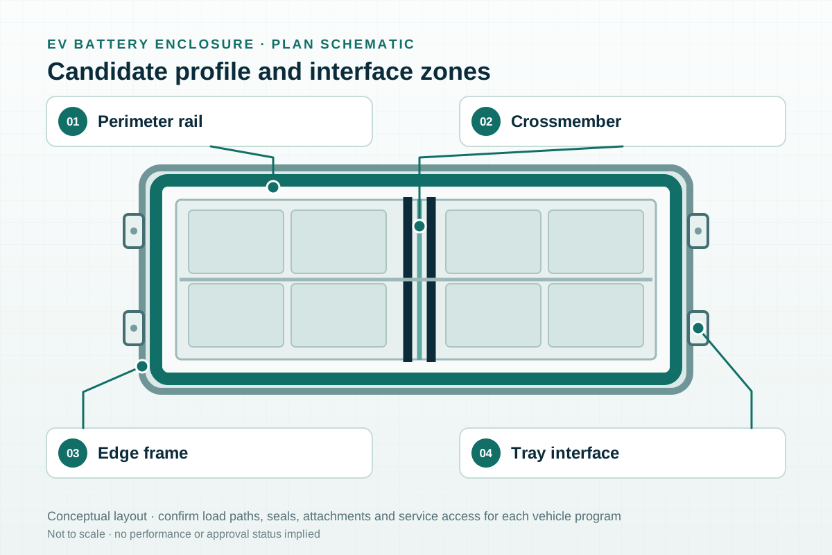
FIG. 3 EV battery packs
Technical illustration marking candidate perimeter-rail, crossmember, edge-frame and tray-interface zones in an EV battery enclosure; conceptual, not an F1-supplied pack

Components to evaluate

  • Battery-pack cross rails and end members
  • Cell restraint or compression-bar profiles
  • Cover-edge and underbody-shield edge profiles

Pack-level checks

  • Crush, impact, vibration and attachment load paths
  • Sealing, thermal movement, coolant and moisture exposure
  • Electrical insulation and fire behavior of the assembled configuration

04 · Trucks & refrigerated bodies

Coordinate body rails with the wall and cargo duty

Truck and trailer bodies have long roof, floor and wall details. A refrigerated body adds insulation and sealing, so its sideposts must be assessed as part of the complete wall rather than as isolated profiles.

Candidates include box-body roof and floor edge rails, wall sideposts, liner fixing rails and door-edge details. A chassis crossmember or other primary vehicle member carries different safety and durability duties and needs a separate OEM-led program. For the body details, set cargo-restraint and handling loads, repeated door cycles, support spacing and replacement strategy before choosing a section.

In a refrigerated wall, the sidepost geometry must suit panel spacing, insulation thickness and liner fastening. A fiberglass post conducts less heat than a metal post and reduces the thermal bridge through the wall, but energy use cannot be inferred from the profile alone. Compare complete wall or body assemblies under the same test method, including skins, foam, joints, doors and air leakage. Validate cargo impact, fastener pull-through, moisture ingress and temperature cycling alongside thermal performance.

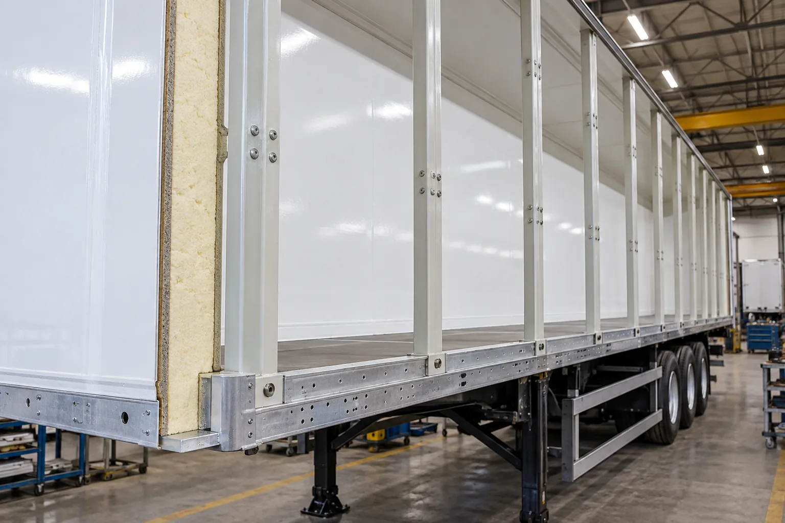
FIG. 4 Trucks & refrigerated bodies
Cutaway of a refrigerated trailer wall showing fiberglass sideposts, insulated panels and an interior liner

Components to evaluate

  • Truck-body roof, floor and wall edge rails
  • Insulated-wall sideposts and liner fixing rails
  • Door-edge, corner and panel-support details

Design and approval checks

  • Body loads, cargo impact and fastener pull-through
  • Wall-level heat transfer, sealing and condensation risk
  • Washdown, road salt, moisture ingress and repair access

05 · Rail vehicles

Assign the fire requirement to each component before choosing the resin

Railcar body details need repeatable dimensions, a durable surface and clear installation interfaces. Pultruded profiles can be evaluated for roof-edge and skirt details, window reveals, interior ceiling supports, luggage-rack elements and cable covers.

These parts may be bonded or mechanically fixed to a metal carbody. The joint must transfer the specified service loads and accommodate tolerances, temperature movement, vibration and maintenance access. For exterior pieces, review weathering, cleaning agents and finish repair. For interior pieces, include passenger contact, fixture loads and the complete installed configuration in the design review.

Fire performance is assigned to the particular component and its operating context. The rail customer should state the applicable requirement set and hazard level under EN 45545-2 or the governing local standard. Ask for test evidence for the offered resin, reinforcement, surface veil, coating and assembly; a generic statement about phenolic or fire-retardant resin is not product approval.

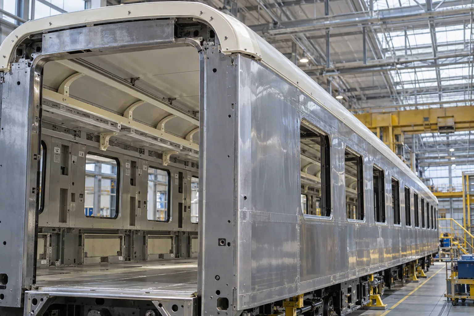
FIG. 5 Rail vehicles
Unfinished railcar body with light-colored ceiling support rails inside a metal shell

Components to evaluate

  • Roof-edge, sidewall and skirt support details
  • Interior ceiling, luggage-rack and window-surround profiles
  • Cable-cover and equipment-enclosure sections

Design and approval checks

  • Applicable fire requirement set, hazard level and tested configuration
  • Bonded or bolted joint evidence and fatigue loads
  • Exterior weathering or interior wear and cleaning regime

06 · Specialty vehicles

Separate access-panel details from safety-critical load paths

Utility, maintenance and other specialty fleets carry equipment in wet, dirty and frequently washed compartments. FRP profiles can be considered for equipment-door frames, removable panel edges, cable-protection covers and secondary mounting rails.

The useful boundary is the component and its function. A profile that supports an access panel is different from a crash member, occupant restraint anchor or lifting point. The vehicle designer must identify those safety-critical load paths and approve any material change before supply.

Define the actual exposure: road salt, detergents, oil mist, sunlight, standing water or chemical splash. Resin selection, finish, drainage and compatible hardware follow from that service profile. Where field repair matters, agree on a replaceable joint and inspection method early in the design.

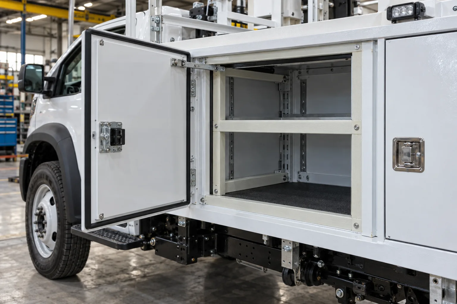
FIG. 6 Specialty vehicles
Service vehicle equipment compartment with fiberglass panel edging and secondary support rails

Components to evaluate

  • Equipment-door and removable-panel frames
  • Cable-protection covers and compartment edging
  • Secondary rails for approved equipment attachments

Design and approval checks

  • Equipment mass, local loads and access-door cycles
  • Chemical, UV and road-salt exposure
  • Inspection, replacement and compatible fasteners

Match a starting profile to the component duty

A direct copy of a steel or aluminum section may miss the stiffness, crash response or joint performance required of a composite. Use these starting shapes to frame the inquiry; final geometry and material follow the installed-part requirements.
Candidate componentStarting profileWhat decides the specification
Bus skirt, luggage rack or duct supportCustom flange, channel or hollow sectionFixture, debris or latch loads; joint fatigue; finish; fire scope
Passenger-car bumper, sill or seat memberCustom multi-cell or reinforced beam sectionOEM crash or restraint cases; load path; inserts and repair
EV pack rail, cell restraint or cover edgeCustom rail, bar or edge profilePack crush; clamp retention; seal; electrical and fire duty
Truck body or refrigerated-wall sidepostCustom rail or sidepost matched to the wall stackCargo impact; fastening; sealing; complete-wall thermal test
Rail exterior or interior detailCustom rail, cover or formed edge profileFire requirement set; joint fatigue; finish and access
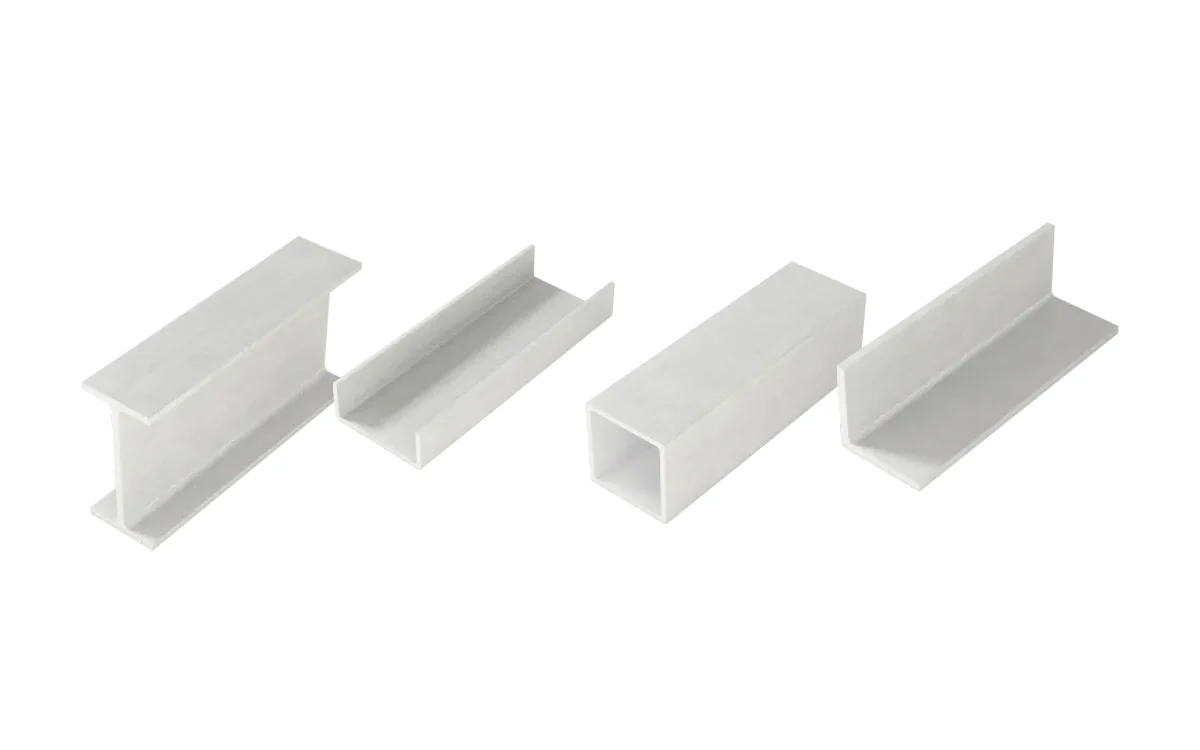
Specialty body compartmentCustom section, or a standard tube or angle verified for the dutyEquipment loads; exposure; service replacement
  • Specify the supplied state

    State whether the order covers raw lengths, cut and drilled parts, coated pieces or an assembly. The drawing should identify critical dimensions, appearance, inserts and the inspection points needed for that state.

  • State the acceptance basis per component

    Crash, restraint and high-voltage parts follow the OEM's or system supplier's tests. For refrigerated bodies, compare finished walls or bodies for thermal performance; for rail, specify the component's fire requirement set and hazard level.

From profile concept to an approved vehicle part

The useful comparison is between a defined component and its proposed replacement. Geometry, laminate, joints and the qualification route must be reviewed as one design.

Choose the process from the part geometry

Pultrusion is a route for straight, constant-section geometry. A panel or three-dimensional shell may need another process, even when a pultruded edge or stiffener remains useful.

  1. 01 · Pultruded profile

    Long, repeatable section

    Start here when the part can keep one cross-section along its length: a rail, edge frame, hollow member or panel stiffener. Define the installation envelope, the load direction and every joint before drawing the die.

    Candidate parts: Bus roof and duct rails, luggage-bay edges, body panel stiffeners and battery enclosure perimeter details.

  2. 02 · Assembly design

    Profile integrated into a panel

    A pultruded edge or stiffener can be evaluated with a sandwich panel or molded part. The adhesive, fasteners, local inserts and panel skins then become part of the load path and the test article.

    Candidate parts: Honeycomb panel edges, access covers and insulated vehicle walls.

  3. 03 · Molded part route

    Large three-dimensional surface

    A roof shell, front or rear cover with changing section and compound curvature normally needs a molding route such as resin transfer molding (RTM), vacuum infusion or SMC compression molding. Specify the shell separately, then decide whether a pultruded rail has a useful interface role.

    Candidate parts: Body covers, large exterior skins and complex battery covers.

Define the laminate and the evidence together

Automotive qualification uses the offered laminate and finished detail. The fiber (E-glass, carbon or a hybrid), the resin family, transverse reinforcement, surface veil and coating are choices to evaluate against the same drawing and duty cycle. Test values belong to the specified construction and specimen.

Design decisionQuestion for the vehicle programEvidence to request
Reinforcement and directionWhere do the bending, axial, transverse and local bearing loads enter the part?Longitudinal and transverse material data, local joint specimens and full-section tests where the component requires them.
Resin and surfaceWhat are the heat, moisture, salt, cleaning, fire, electrical and finish requirements?A named resin and laminate build, finish specification and reports for the proposed formulation and test configuration.
Geometry and assemblyWill the section fit the mounting envelope after cutting, drilling, coating and temperature cycling?A datum-based drawing, first-article dimensions, curvature fit where needed, coating bake distortion checks, galvanic isolation of carbon or hybrid laminates from aluminum or steel hardware, and an approved fastening or bonding procedure.
Service life and approvalWhich loads repeat, which failures matter, and who accepts the finished component?Part-level fatigue, vibration, impact or creep evidence as specified by the OEM, plus an agreed production inspection plan.

Move from concept to a controlled part

  1. 01

    Freeze the duty and interface

    Mark the part on the vehicle drawing. Set loads, support points, allowable movement, temperature range, surface class and the OEM's applicable acceptance requirements.

  2. 02

    Build a representative profile

    Review the die concept, wall and corner geometry, fiber architecture, resin and finish. Produce samples with the intended material and process.

  3. 03

    Test the installed detail

    Measure fit and tolerances, then test the load path through the actual bond or fastener layout. Add cyclic, impact, thermal, fire or dielectric testing according to the component's duty.

  4. 04

    Set the supply controls

    Set drawing revision, critical dimensions, inspection frequency, material traceability, finish limits and change control before repeat orders.

Start with a marked drawing and the acceptance basis. We can review the profile and test scope through our custom pultrusion process.

Documents

  • Data sheetPDF · 3 MB

    FRP Profile Design Manual — DOC-PF-2026-EN Rev. B

    Issued by
    F1 Composite
    For
    Structural shapes

    Revision B (October 2026), generated from the website's catalog, laminate and design-basis data: EN 13706 E23 laminate values beside the grade minimums, section properties of all 114 catalog sizes, allowable uniform loads to the published LRFD screening basis, application guides, durability stated by resin formulation, fabrication and inspection. A preliminary-sizing reference, not a project approval or batch certificate; it supersedes the withdrawn Rev. A.

  • Data sheetPDF · 8 KB

    PU-GF Pultruded Profile — Mechanical Data Sheet

    Issued by
    F1 Composite
    For
    Custom pultrusions

    The material system and methods identified in the sheet. Confirm whether each value is typical, measured or a design value before applying it to another laminate or section.

  • CertificatePDF · 142 KB

    EPD & Carbon Footprint — Pultruded GFRP Composite Profiles

    Issued by
    CABR
    For
    Standard profiles

    Environmental Product Declaration and product carbon footprint analysis for F1 Composite pultruded GFRP composite profile products, with 1 m² functional unit. Calculation reference CABR-CFC-01(02)-2025(20030)1, cradle-to-gate 33,934.34 g CO₂e/m², distribution 254.59 g, cradle-to-grave 36,099.32 g. Standards: GB/T 24025-2009 (ISO 14025-aligned Type III EPD), GB/T 32161-2015, ISO 14067, PAS 2050. Issued by China Academy of Building Research Co., Ltd. (CABR) Certification Center on April 30, 2025.

  • CADOn request

    Standard Profiles — CAD Library

    Issued by
    F1 Composite
    For
    Standard profiles

    2D and 3D CAD models for all standard I-beam, channel, angle, and tube profiles.

  • CatalogOn request

    Product Catalog 2024

    Issued by
    F1 Composite
    For
    All products

    Complete catalog of standard pultruded FRP profiles with dimensions, properties, and ordering information.

  • CertificateOn request

    ISO 9001:2015 Certificate

    For
    All products

    Request the current quality-management certificate holder, validity and scope for your proposed supply.

  • CertificateOn request

    CE Declaration of Performance

    For
    All products

    Request product-specific performance and applicable conformity documentation; confirm the intended use and assessment route.

All downloads and CADTest reports and their scope

Questions buyers ask

Can a pultruded FRP profile replace a steel bumper beam or side sill?

It can be evaluated as a candidate, but a drawing substitution is insufficient. The OEM must compare the complete crash pulse, energy absorption, intrusion, attachment loads, environmental aging and repair behavior of the proposed part and its joints. F1 can discuss a custom constant-section profile; qualification of a crash or occupant-safety component belongs to the vehicle program.

Are seat crossmembers or seat back frames suitable for pultrusion?

Constant-section members can be investigated, but seat and restraint load paths are safety-critical. The vehicle and seat-system engineers must set the static, dynamic, fatigue, anchorage and misuse cases before a material or cross-section is chosen.

Can one FRP material serve every EV battery-pack part?

No. A pack rail, cell restraint, cover edge and underbody-shield edge have different loads and thermal, fire, sealing and electrical duties. Moisture, conductive inserts and nearby metal can change the insulation behavior of the assembled part. Define the location and pack-level acceptance tests before selecting a laminate or claiming an electrical benefit.

How should a vehicle weight saving be calculated?

Compare parts that meet the same performance targets, including the redesigned section, inserts, adhesive, fasteners and protective finish. A same-volume density comparison is only a material comparison: composite stiffness, joining and crash behavior can change the geometry and installed mass.

Which fire requirements apply to bus and rail interiors?

The customer identifies the vehicle class, part location and governing market. Bus materials may have requirements under UN Regulation No. 118 or local rules; rail projects may specify EN 45545-2 requirement sets and hazard levels. Resin type alone does not establish compliance. Review reports for the offered formulation and finished configuration against the exact project requirement.

Will fiberglass sideposts reduce a refrigerated body's energy use?

A fiberglass sidepost conducts less heat than a metal one and reduces the thermal bridge through an insulated wall, but whole-body performance also depends on insulation, skins, doors, joints and air leakage. Compare wall or body assemblies under the same test conditions, and check cargo impact, fastening, sealing and condensation before predicting refrigeration energy use.

What evidence is needed before series supply?

The listed parts are engineering candidates, not claims of F1 supply to a vehicle program or an OEM partnership. Before series supply, agree on the drawing, laminate, interfaces, component tests, dimensional and visual inspection, traceability and the vehicle maker's approval route. The exact evidence follows the part's safety function and governing market.

Quote FRP for automotive & rail

Send the part drawing, load cases and vehicle interface with the required acceptance tests. We can then review whether a pultruded profile suits the geometry and define the proposed supply and test scope. We reply within one business day; a formal quotation follows once the specification and delivery are reviewed.

Part geometry and function
Vehicle type, marked component location, section envelope and length; send 2D/3D drawings and identify the load path and adjacent parts.
Load cases and interfaces
Static, impact, crash and fatigue cases as applicable; support spans, allowable movement, mating materials, insert locations and bond or bolt design.
Environment and acceptance
Temperature range, water, salt, cleaners, UV, electrical proximity and fire exposure; list the component standards, test methods and approval evidence required by the OEM.
Prototype and production
Target mass, cut length, tolerances, finish, machining, first-article quantity, annual forecast, inspection and traceability requirements.
Get a quoteWhatsApp