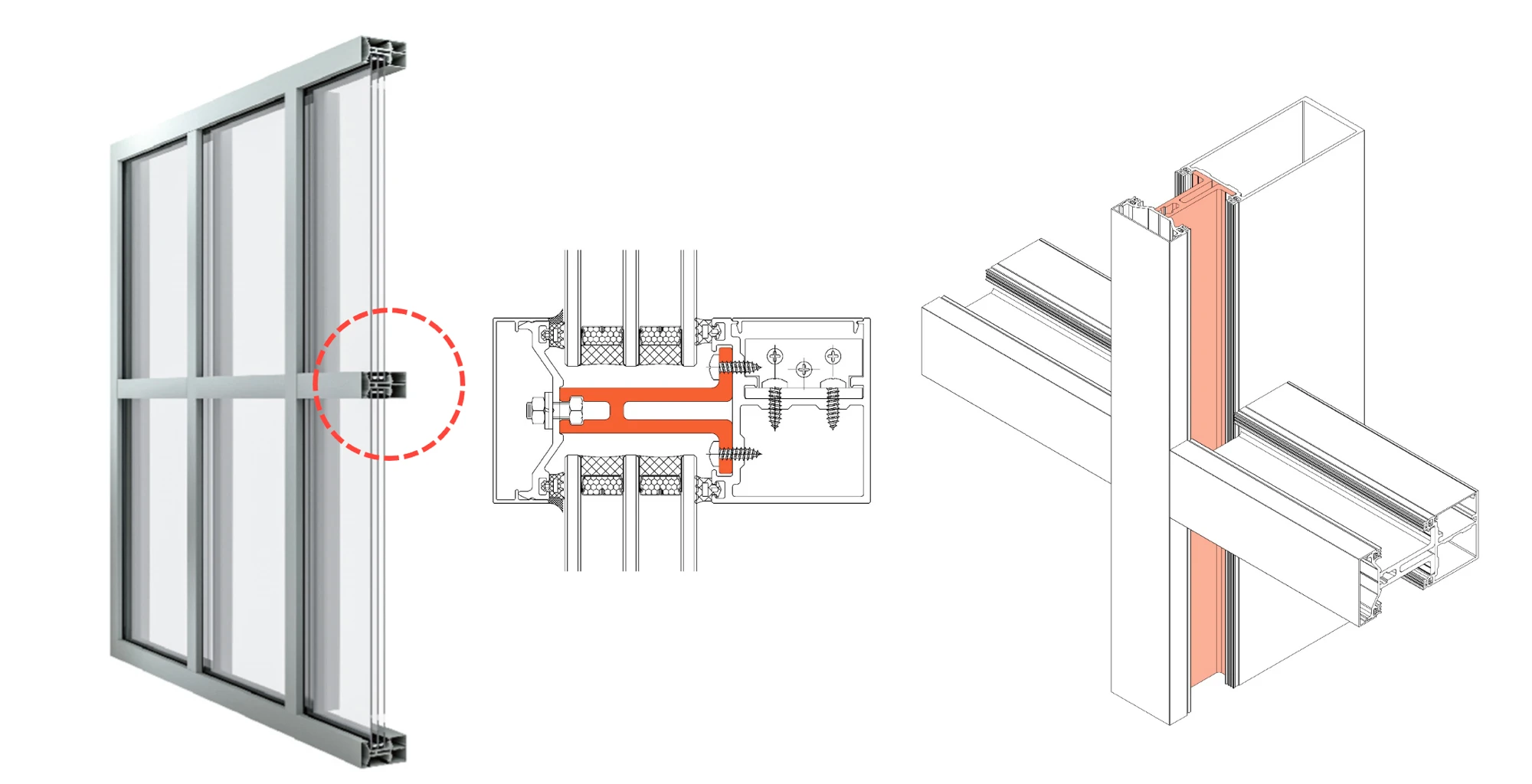
Look at the cross-section of any thermally broken stick curtain wall and find the smallest structural part in the drawing. It is not the mullion, not the pressure plate, not the glass. It is the isolator: the insulating profile that separates the exterior aluminum from the interior aluminum. In the section drawing it reads as a detail. In the load path it is a primary structural member: every force the glazing collects passes through it, every hour, for the design life of the building envelope.
This article is about that distinction: the isolator as a structural member rather than a spacer. Because the moment you treat the curtain wall isolator as a structural member with a 25–50-year service life, the material question stops being "what insulates?" and becomes "what carries sustained load, in the awkward direction, at the thermal boundary, for decades?" And that question has a different answer than the one the industry inherited from window systems.
What the isolator does in a stick curtain wall
In a pressure-plate (stick) curtain wall, the glass units sit in front of the mullion and transom grid, retained by an exterior aluminum pressure plate that clamps the glass edge through EPDM gaskets, and closed with a decorative cover cap. Between the pressure plate and the mullion body sits the isolator profile (typically an H, I, or T section) through which the clamping screws run.
The isolator has two jobs at once. Thermally, it is the break: it interrupts the metallic path between the exterior aluminum (at nearly outdoor temperature) and the interior aluminum (at nearly room temperature), and its conductivity largely decides the frame contribution to the curtain wall U-value under EN ISO 10077-2. Structurally, it is the bridge: wind suction on the glass pulls the pressure plate outward, the pressure plate pulls the screws, the screws pull the isolator, and the isolator transfers that tension into the mullion. There is no redundant path around it.
The isolator also lives exactly on the thermal gradient it creates. Its outer face tracks the exterior (down to −20 °C and below in cold climates) while its inner face sits near +20 °C. This is why EN 14024, the governing standard for thermal barrier profiles in metal framing, tests mechanical performance across the full range: transverse tensile and longitudinal shear characterized at low temperature, room temperature, and +80 °C.
Why this is not a window thermal-break strip
The polyamide strip in a thermally broken aluminum window and the isolator in a curtain wall get called by the same name, and that shorthand causes real specification errors. The parts do different jobs:
| Aspect | Window thermal-break strip | Curtain wall isolator |
|---|---|---|
| Position | Rolled and crimped into the aluminum extrusion | Screwed between pressure plate and mullion/transom |
| Structural role | Composite shear action within the frame member | Primary load path for the glazing retention |
| Dominant loads | Frame bending shared with aluminum | Screw clamp preload, wind suction tension, glass dead load |
| Load duration | Mostly short-term (wind, operation) | Sustained 24/7 (clamp preload, glass weight) plus cyclic wind |
| Consequence of failure | Frame stiffness loss | Loss of glass retention and weather seal |
| Replaceability | With the window | Only by de-glazing the facade |
Four load components make the curtain wall case harder than the window case.
Clamp preload, sustained. The pressure-plate screws (typically every 200–300 mm along every mullion and transom) are torqued at installation and stay torqued for the life of the wall. That preload is a permanent compression and thread-engagement load in the isolator. If the isolator material creeps or relaxes, clamp force decays: gaskets lose compression, air and water performance degrade, and in the worst case the glazing retention itself softens.
Wind suction, fully reversing. Positive wind pressure pushes the glass onto the interior gasket and largely bypasses the isolator. Suction does the opposite: the entire negative load on the glass panel arrives at the isolator as transverse tension and screw pull-out. On a high-rise corner zone this is a large, cyclic, decades-long fatigue load, and it acts across the isolator profile, not along it.
Glass dead load at the transom. This is the case that separates serious isolator design from catalog selection, and it gets its own section below.
The thermal gradient itself. The isolator spans the temperature difference the rest of the system is protected from, so its mechanical properties must hold at the temperature extremes simultaneously (a cold outer flange and a warm inner flange) through every daily and seasonal cycle.
The service-life requirement changes the material question
A curtain wall is designed as a permanent building envelope. European practice (EN 13830, CWCT guidance) and project specifications commonly put its service life at 25 years minimum and often 50. The isolator is buried in the system: replacing it means removing cover caps, pressure plates, and glass, effectively re-glazing the elevation. So the isolator must be specified on its end-of-life properties, not its day-one datasheet.
That is uncomfortable for the incumbent material. Glass-reinforced polyamide (PA66 GF25) is an excellent engineering polymer and the deserved standard for window thermal-break strips. But it is a thermoplastic that absorbs moisture, around 2.5–3% at saturation, and conditioned properties fall well below the dry-as-molded values on the datasheet. It creeps measurably under sustained load, which is precisely the load type a curtain wall isolator carries. And at fire temperatures it melts rather than chars, which for a part whose job is holding the pressure plate on is worth thinking about carefully.
Pultruded thermoset GFRP approaches the same job from the other side. Moisture uptake is roughly an order of magnitude lower, and there is no plasticization mechanism: properties do not step down when the profile gets wet. The thermoset matrix does not melt; in fire it chars in place. Thermal conductivity is comparable to filled polyamide at roughly 0.3 W/m·K, so the thermal calculation is essentially neutral in the swap. The one place where conventional pultrusion genuinely struggles for this application is directional: everything difficult about the isolator load case happens across the profile axis, and a standard pultrusion is weakest exactly there. Which brings us to the transom.
The transom is the hard case
Run the numbers on a modern glazing unit. Glass weighs about 2.5 kg/m² per millimeter of thickness. A double IGU with two 6 mm lites is 30 kg/m²; a triple with three 6 mm lites is 45 kg/m². A 2.5 m × 3.0 m triple-glazed unit, unremarkable on a current commercial facade, weighs around 340 kg, and all of it bears on two setting blocks near the ends of the transom below. Depending on the system detail, that dead load enters the transom through the glazing rebate or through support brackets at the isolator line. Either way, the transom isolator region carries a sustained load in the range of 1.5–2 kN near each setting block, every hour of the building's life, before wind ever blows.
Now look at the direction of that load. The transom isolator is pultruded along the transom, horizontally. The glass weight acts vertically: transverse to the fiber axis. The clamping screws engage perpendicular to the fiber axis. Wind suction pulls perpendicular to the fiber axis. On a transom, essentially every load the isolator carries is a 90° load.
Conventional pultrusion is built the other way. A standard profile is mostly unidirectional roving with a chopped strand mat skin: full-section modulus of 23–40 GPa along the axis (the EN 13706 E23 grade and above), but only about 7–10 GPa across it, a 0°:90° ratio of 4–5:1. Worse than the stiffness ratio is the load-carrying mechanism behind it: transverse stress in a roving-and-mat laminate is carried substantially by the resin matrix. Under short-term load that is manageable. Under a sustained transverse load held for 25–50 years, matrix-dominated load paths creep, and creep in the part that holds the clamp force is exactly the failure mode a facade engineer cannot accept.
Balancing 0° and 90°: the multi-layer multiaxial laminate
This is the problem F1 Composite's curtain-wall isolator laminate was developed to solve. Instead of roving plus surface mat, the isolator profiles are built as a multi-layer stack of stitched multiaxial fabrics (0°, 90°, and ±45° non-crimp layers distributed through the full thickness of the section) over a reduced unidirectional core. The design goal is stated in one line: bring the 90° elastic modulus into balance with the 0°.
| Property | Conventional pultrusion (roving + CSM) | F1 multi-layer multiaxial laminate |
|---|---|---|
| 0° modulus | 23–40 GPa | Tuned to the profile |
| 90° modulus | 7–10 GPa | Raised to the same order as the 0° |
| 0°:90° ratio | 4–5 : 1 | 2 : 1 down to near 1 : 1 where the detail demands |
| Sustained transverse load carried by | Resin matrix (creeps) | Continuous glass fiber (negligible creep) |
| Screw pull-out and thread engagement | Matrix and mat dependent | Backed by 90°/±45° fabric layers |
| Local bearing at setting-block loads | Prone to matrix-dominated crushing | Fiber-supported in both directions |
The structural consequence matters more than the stiffness numbers. With continuous 90° and ±45° fibers crossing the transverse load path, glass fiber rather than polymer carries the glass dead load on a transom isolator. At these stress levels E-glass creeps by amounts that are negligible next to a polymer matrix or a thermoplastic. Clamp preload relaxes less. Screw threads engage a laminate with fabric behind every flank. The web-to-flange junction of an H-isolator, bending across the profile under suction, is a fiber-dominated detail instead of a matrix-dominated one.
This is the same laminate philosophy behind our transverse-reinforced fenestration architecture and the E40 facade sunshade plate: pultrusion's historical weakness is the 90° direction, and the fix, within the same process, is to put engineered fabric where the load actually goes. For isolators the fabric stack is tuned per profile: a mullion isolator that mostly sees suction tension gets one balance point; a transom isolator under permanent gravity load gets another, pushed toward 1:1.
Testing and standards: what to ask for
Specify curtain-wall isolators against the load case, not against a material name. The relevant framework:
EN 14024: the mechanical performance standard for thermal barrier profiles in metal framing: transverse tensile and longitudinal shear, characterized at −20 °C, room temperature, and +80 °C, with category classification. Ask for the isolator's test values at all three temperatures, because the part operates across that whole range at once.
EN 13830: the curtain walling product standard, which frames the system-level performance (wind resistance, air, water, impact) the isolator must survive inside, and the service-life expectation it must match.
EN ISO 10077-2: the two-dimensional thermal calculation in which the isolator's conductivity and geometry set the frame U-value contribution. Pultruded GFRP at approximately 0.3 W/m·K slots into existing thermal models in place of filled polyamide with minimal change.
AAMA TIR A8: the North American engineering reference for composite thermal barrier framing, useful for projects specified on the AAMA side of the ocean.
For sustained-load behavior, the transom case, ask any supplier one direct question: what carries the transverse load after year ten, fiber or matrix? A laminate drawing answers it faster than a datasheet.
What to send us, and what you get back
Isolator profiles are system-specific by nature: the cross-section must match the pressure-plate system, screw spacing, gasket geometry, and glazing weight of your curtain wall. We produce them through the custom pultrusion program: dies up to a 600 × 300 mm envelope, H / I / T / U and system-specific geometries, machined screw channels, cut to length and CNC-drilled where required, in fire-retardant resin systems where the facade specification calls for them.
Send the system cross-section, the maximum glass unit weight, the wind report or design pressures, and the specified service life. What comes back is a proposed isolator section with its laminate specification (including the 0°/90° balance chosen for the mullion and transom cases separately) EN 14024-oriented test data, and pricing at production quantities. If you are earlier in the design than that, our KNOWHOW engineering service can start from the facade drawings instead.
Bottom line
The curtain wall isolator was never really a thermal part with a structural footnote. It is a structural part whose material happens to insulate. Once the service life is 25–50 years and the governing loads are sustained and transverse, the material requirement reads: no moisture step-change, no melt point, no matrix-dominated creep path under permanent load, mechanical properties proven from −20 to +80 °C, and a laminate stiff in the direction the glass actually pushes.
Conventional pultrusion met most of that list and missed the last item. Balancing the 0° and 90° moduli with a multi-layer multiaxial fabric stack closes it, and turns the smallest part in the curtain wall drawing into the one you no longer have to worry about.