FRP profiles for waterfront retaining walls
A waterfront wall connects ground engineering, hydraulic conditions and a structural section. Use this guide to prepare a custom FRP sheet-pile inquiry with the site information needed to evaluate a suitable wall system.
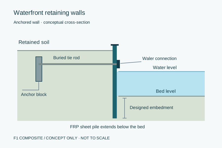
Where it fits and what we supply
The inquiry covers interlocking sections and agreed caps, corner pieces or connection components. Confirm design responsibility, geotechnical work, accessories and installation separately in the project scope.
This page describes how the products are used; design and installation are included only where the quotation says so.
Products for this application
Recommended profiles and resin
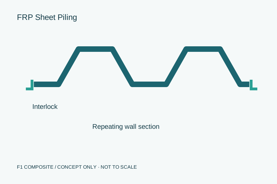
- 01Interlocking sheet-pile sections selected for the wall geometry
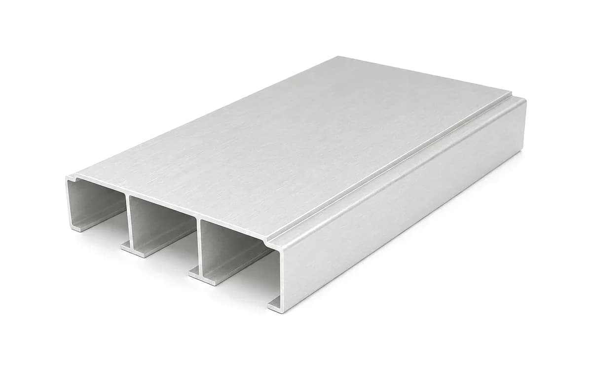
- 02Capping sections and corner transitions matched to the interlocks
- 03Walers and connection components reviewed as part of the anchor layout
Resin
Provide soil and water chemistry, salinity, abrasion, temperature and UV exposure. Review durability evidence and resin suitability for both submerged and exposed portions.
Standards commonly referenced
- ASCE/SEI 74-23 · pultruded members
- CEN/TS 19101:2022 · FRP structures
- ASTM D7290 · characteristic values
- EN 1997-1 · geotechnical design
- USACE EM 1110-2-2504 · sheet pile walls
Specification and test references, not certifications of a product.
Design and specification checks
Check 1
Ground and water
Provide soil strata, groundwater and surface-water levels, surcharge and scour conditions. The designer establishes embedment, drainage and global stability.
Check 2
Wall and connections
Use properties for the offered section to check long-term bending, shear, local stability, interlock loads and anchor connections. Define movement and leakage acceptance criteria.
Check 3
Installation access
Review delivery lengths, lifting points, working space and the driving method. A trial in representative ground helps establish protection and acceptance procedures.
Design the wall for stiffness, sustained pressure and its exposed face
Serviceability usually governs a composite wall. EN 13706 grade E23 sets a minimum longitudinal modulus of 23 GPa; use verified properties for the offered section when checking wall deflection and anchor movement. Earth and water pressure act for the whole service life, which brings creep deflection and a sustained-stress limit into the design; request creep evidence for the offered section rather than relying on short-term coupon values.
Interlocks transfer shear between piles and control seepage, and the zone between low water and the cap sees UV, abrasion, impact and wet-dry cycling. Review durability evidence for the submerged and the exposed portions separately, and confirm the driving method, since thin-walled sections often need a mandrel or guide frame.
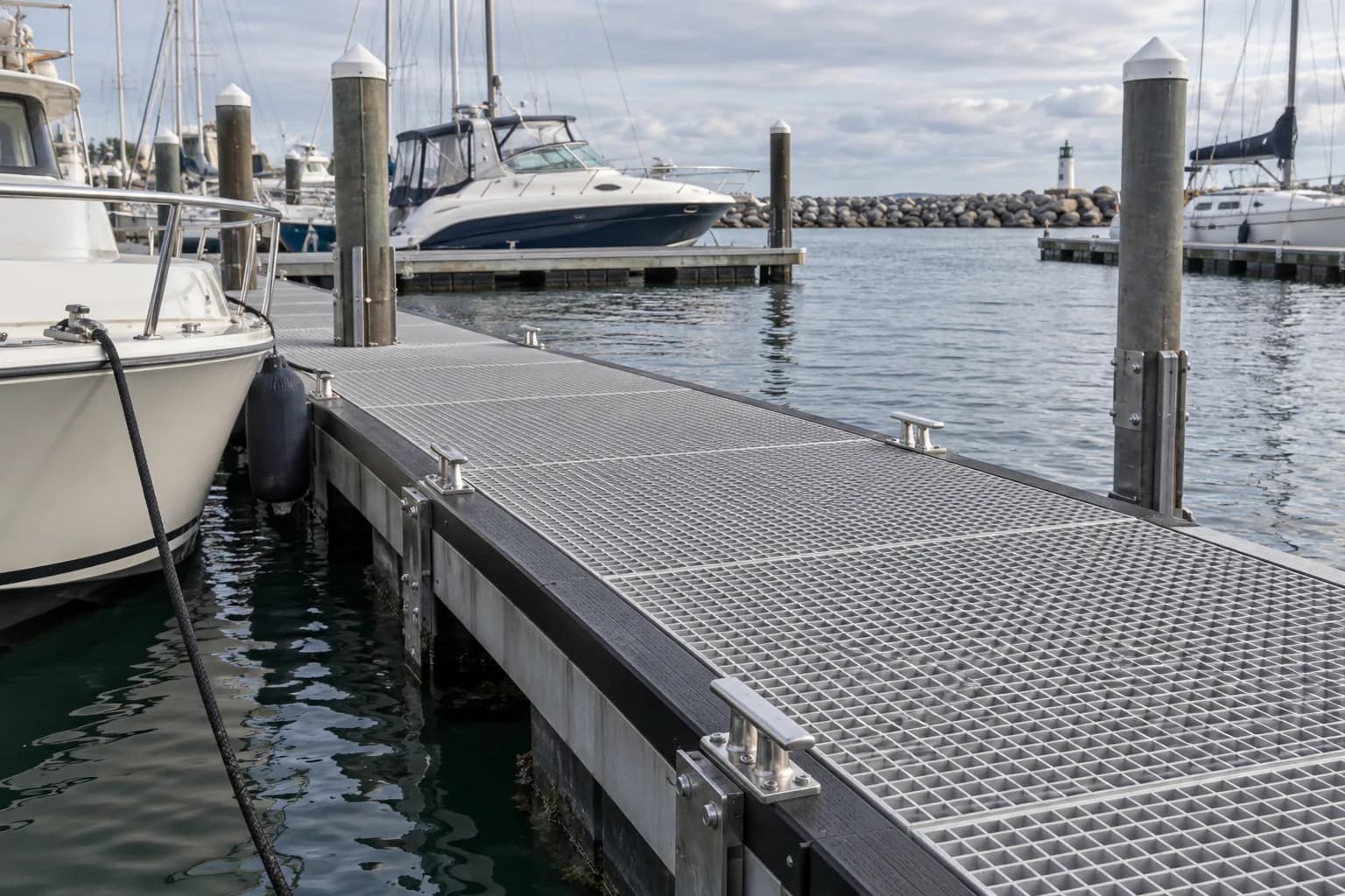
Where a boardwalk or deck meets the wall, define the interface between the wall cap, deck supports and any railing: how loads transfer into the wall, whether connections accommodate movement and which party designs each interface.
Quote Waterfront retaining walls
Send the inputs below with a drawing or sketch, and the destination. We reply within one business day; a formal quotation follows once the specification and delivery are reviewed.
- Wall plan, sections and retained levels
- Geotechnical information and design water levels
- Loads, movement limits and required design life
- Tie rods, walers, corners and sealing requirements
- Proposed installation method, quantities and destination