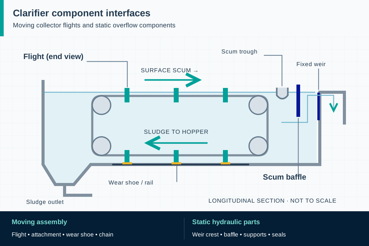
For a moving flight, provide the distance between attachment points, wear-shoe positions, travel direction and collector operating conditions. The equipment designer should establish the applicable bending, twisting, cyclic and abnormal operating cases. Review profile deflection against available clearances, and check the web and flanges locally at fasteners. A coupon strength alone does not demonstrate the behavior of a drilled flight over its installed span.
For a stationary plate, establish the relevant water levels on each side and the conditions during filling, draining, blockage or maintenance. The support arrangement transfers those reactions into existing concrete or steel. Include anchors, brackets, local plate bearing and joint stiffness in the review. Never assume the basin wall or old anchor holes can accept a revised arrangement without examination.
Define a drawing datum for every critical hole and mounting surface. Include slots or adjustment details only where the designer intends them. A connection detail must balance assembly tolerance, movement and restraint; adding extra field holes to make a part fit can remove material from a critical section and invalidate the reviewed load path.