Skip to content
Pultrusion application guide

Carbon-fiber components for industrial rollers

A light tube is only the starting point for a production roller. The working surface, end connections, bearings and rotating assembly must deliver the required web handling, dimensional accuracy and machine behavior together.

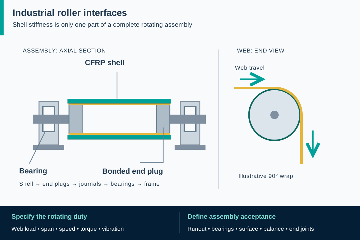
FIG. 1 Carbon-fiber industrial rollersApplication schematic · not to scale
The axial section connects shell, plugs, journals, bearings and frame. The separate end view shows tangent web entry and exit around a quarter-turn wrap.

Component scope and material selection

F1 can review a CFRP component feasibility and qualification inquiry. Precision finishing, end fittings, balancing, bearings and qualification of a finished roller must be separately defined and confirmed; they are not assumed supply capabilities.

Select the complete material system

Application-specific CFRP tube construction, potentially requiring transverse or angled reinforcement as well as longitudinal fibers.

Components to specify

  • Candidate CFRP roller shells
  • Longitudinal reinforcement for an engineered hybrid shell
  • Tube components with agreed machining and surface allowances

Identify the roller's process duty

A free-running guide roller redirects a moving web. A driven roller transfers torque, while a contact or process roller may carry a controlled nip load or apply a coating. Printing parts introduce further demands on mounting and the working surface. Before comparing materials, identify the duty and the production problem: excessive deflection, difficult handling, unstable tracking, vibration, surface damage or inadequate response during acceleration.

Carbon roller applications are documented in film converting, printing and nonwoven machinery. Those examples involve engineered assemblies rather than interchangeable black tubes. A retrofit must preserve the machine interfaces and process geometry. Record the existing bearing arrangement, drive connection, web path and adjustment range, including conditions during threading, start-up and a process upset. These inputs explain what a candidate replacement must actually accomplish.

ReferencesEpsilon Composite: technical carbon rollers

Choose reinforcement for more than bending stiffness

A predominantly longitudinal reinforcement layout provides the bending stiffness that limits shell deflection between bearings, but a roller also experiences local contact, end restraint and sometimes torsion. The proposed tube architecture should be reviewed against all those actions. Ask what carries hoop and shear loads, how the end region is supported, and whether holes or machined features interrupt important fibers. A catalog tensile modulus is not a complete tube design description.

Industrial examples include pullwinding and structures combining pultruded reinforcement with wound layers. This distinction matters when a purchaser specifies 'pultruded carbon roller': the chosen architecture may require another process or a combination of processes. Confirm the actual construction and manufacturing scope before promising a straight substitution. A plain unidirectional tube should not inherit the properties or operating limits of a proprietary hybrid assembly.

ReferencesEpsilon Composite: technical carbon rollersEpsilon Composite: pultrusion and filament-winding hybrid

Connect web loads to rotor behavior

Provide web tension, wrap angle, contact width and the distances between load application points and bearings. Include nip forces and drive torque where present, together with maximum speed, routine operating speed and acceleration. These allow the responsible engineer to build the loading model and consider deflection, local shell behavior and the end connections. A line-speed figure without diameter and support geometry is an incomplete mechanical brief.

Agree on how the assembled rotor will be assessed across its operating range. Its behavior depends on the shell, journals, bearings, attachments and supports. Balancing reduces the effects of mass eccentricity; it does not remove every possible vibration mechanism. A satisfactory static deflection calculation does not establish a safe dynamic operating range. The machine specialist should identify the relevant rotor behavior, modes and acceptance measurements before choosing a balancing specification. State the first bending critical speed of the assembled rotor and the required margin to maximum operating speed; that margin decides whether rigid-rotor (ISO 21940-11) or flexible-rotor (ISO 21940-12) procedures apply.

ReferencesISO 21940-11:2016: balancing rigid-behavior rotorsISO 21940-12:2016: balancing flexible-behavior rotors

Treat the surface and end fittings as functional parts

Define the web-facing surface by its task: traction, release, marking sensitivity, wear or a process-specific finish. Specify a measurement method and acceptance condition for roughness, profile and run-out. Temperature, process liquids and cleaning agents can affect a coating or an adhesive differently from the carbon laminate. Include both normal operation and cleaning cycles in the exposure schedule rather than asking only whether carbon fiber resists a named chemical.

At each end, identify the route for radial force, axial restraint and torque. Bonded inserts, mechanical retention and bearing seats require their own drawings and evidence. Carbon laminate is electrochemically noble relative to aluminum and steel, so where moisture, process liquid or washdown can reach a metal journal or insert, specify an isolating layer, a sealed interface and drainage, and record the metal grade on the end-fitting drawing. Ask how assembly and disassembly are performed without damaging the shell. Where static control is required, assess the complete path through coatings, end fittings, bearings and the machine; the presence of conductive carbon fibers is insufficient to establish a specified surface or assembly resistance.
ReferencesEpsilon Composite: technical carbon rollers

Commission the assembly in the actual machine

Before installation, compare the delivered item with the approved interface drawing and inspect transport supports, shell condition and protected surfaces. Use the handling and mounting method agreed for the component. Establish how bearing alignment, axial location and drive connection will be checked. If a new roller changes inertia or process response, the OEM should review the relevant machine settings and permitted operating sequence.

Set commissioning stages and stop criteria with the machine team. Useful observations include bearing temperature, vibration, tracking, surface marking and behavior through acceleration and deceleration. Do not infer a permissible test speed from a competitor's brochure. The machine risk assessment must also address access to rotating parts and nip points during threading, operation and maintenance. Changes to a roller can require review of the installation's guards and safe operating procedures.

ReferencesISO 12100:2010: machinery risk assessmentOSHA 29 CFR 1910.212: machine guarding

Make deterioration visible and repair decisions controlled

Record the accepted assembly condition after commissioning so later inspections have a useful baseline. Identify the components that may be serviced by the operator and those that need specialist assessment. The maintenance plan should connect inspection frequency to duty, environment and consequences of failure. Avoid a generic promise that carbon rollers require no maintenance: bearings, coatings and connections remain working parts.

Report changes such as unusual noise or vibration, surface scoring, exposed fibers, looseness at an end fitting or damage after a dropped tool. An apparently small impact can require a closer examination of the laminate. Do not restore appearance by uncontrolled sanding or drilling. Recoating, machining or replacing attachments can change geometry and mass distribution, so define which dimensional, balance and commissioning checks must be repeated after each permitted repair.

ReferencesISO 12100:2010: machinery risk assessmentISO 21940-11:2016: balancing rigid-behavior rotors

Separate tube qualification from finished-roller acceptance

Use a responsibility schedule with separate entries for shell design, tube manufacture, end fittings, finishing, assembly, balancing and machine approval. A component supplier may only cover selected entries. Specify what each delivery includes, which characteristics are still unfinished and who accepts the final assembly. This prevents a tube quotation from being interpreted as a warranted process-performance offer.

A practical development sequence begins with the original machine drawing and duty schedule, then reviews construction options and representative samples before releasing a prototype. Define the evidence needed at each decision point and preserve the identity of the laminate and adhesive processes used. F1 can assess a component inquiry against that brief; stock availability, precision roller production and complete assembly qualification must be confirmed separately for the proposed scope.

ReferencesEpsilon Composite: pultrusion and filament-winding hybridISO 12100:2010: machinery risk assessment

Standards, regulations and acceptance evidence

The project authority determines the governing jurisdiction and adopted edition. The scope of each reference matters: a material test, an equipment requirement and a workplace rule answer different questions.

Standard · International; when specified for the rotor

ISO 21940-11:2016/Amd 1:2022

Balancing procedures and residual-unbalance tolerances for rotors with rigid behavior.

Application boundary: The purchaser must define the applicable rotor configuration, service speed and acceptance criteria. This is not a universal balance grade for every carbon tube or long roller.

ReferencesISO 21940-11:2016: balancing rigid-behavior rotorsISO 21940-11:2016/Amd 1:2022

Standard · International; flexible-behavior rotor applications

ISO 21940-12:2016

Balancing methods and guidance for rotors with flexible behavior.

Application boundary: The official scope does not make it a universal rotor acceptance specification and excludes structural resonances. A satisfactory balance result does not establish the entire machine's vibration performance.

ReferencesISO 21940-12:2016: balancing flexible-behavior rotors

Standard · International machinery risk assessment

ISO 12100:2010

The machine designer's assessment of hazards and risk reduction across intended use.

Application boundary: A carbon tube alone cannot demonstrate conformity of guarding, control functions or the complete machine.

ReferencesISO 12100:2010: machinery risk assessment

Regulation · United States general-industry workplaces

29 CFR 1910.212

Guarding of machine hazards, including rotating parts and ingoing nip points.

Application boundary: Applies to the installed workplace machine and its hazards. It is not an OSHA product approval for a replacement roller.

ReferencesOSHA 29 CFR 1910.212: machine guarding

Public source scopes were reviewed on . These references do not establish certification of an F1 product. Agree the offered grade, finished component, test specimen and acceptance criteria in the project specification.

Carbon-fiber industrial rollers: practical questions

Can a carbon tube replace a metal roller of the same dimensions?

Only after assessment of the complete duty and assembly. Deflection, torsion, local contact, end connections and rotor behavior may require different geometry or reinforcement even when the outer diameter is fixed.

Is dynamic balancing enough to prevent vibration?

No. It addresses unbalance under the agreed conditions. Rotor flexibility, structural resonance, bearings, mounting and process excitation need separate consideration by the machine specialist.

Does carbon fiber automatically make the roller antistatic?

No. Coatings and interfaces can interrupt the required electrical path. Specify the surface and assembly requirements and the method for verifying them in the finished configuration.

Can F1 supply a ready-to-run precision roller?

This page establishes a component inquiry route. A finished roller would require separately confirmed capabilities and responsibilities for the shell, end fittings, precision surface, bearings, balancing and machine acceptance.

Technical sources and further reading

Industry sources establish where the application is used. Authority sources define the published scope of standards and regulations. The design and procurement checklists above are an original engineering synthesis for project review.
  1. Industry application evidence

    Epsilon Composite: technical carbon rollers

    Application evidence for converting, printing and nonwoven machinery. Describes pullwinding and hybrid manufacture; its finished-roller claims do not establish F1 capabilities.

  2. Industry application evidence

    Epsilon Composite: pultrusion and filament-winding hybrid

    Explains that some high-performance tubes combine pultruded reinforcement and wound layers. K1 is a proprietary process, not an F1 process claim.

  3. Standard or public authority

    ISO 1101:2017: geometrical specification language

    Official scope for indicating and interpreting form, orientation, location and run-out requirements. It does not set a roller tolerance or inspection support arrangement; the purchase checklist is original project guidance.

  4. Standard or public authority

    ISO 5459:2024: datums and datum systems

    Defines the indication and interpretation of datums in technical documentation. Its public scope excludes the verification operator; measurement fixtures and conditions need separate agreement.

  5. Standard or public authority

    ISO 21940-11:2016: balancing rigid-behavior rotors

    Official scope for balancing procedures and tolerances when the rotor has rigid behavior.

  6. Standard or public authority

    ISO 21940-11:2016/Amd 1:2022

    Published amendment to Part 11; establish the contractual edition and amendments with the purchaser.

  7. Standard or public authority

    ISO 21940-12:2016: balancing flexible-behavior rotors

    Official scope and limitations for flexible rotors, including the exclusion of structural resonance assessment.

  8. Standard or public authority

    ISO 12100:2010: machinery risk assessment

    General machinery design, risk assessment and risk reduction; not a material certification.

  9. Standard or public authority

    OSHA 29 CFR 1910.212: machine guarding

    US workplace requirements concerning machine hazards such as rotating parts and ingoing nip points.

Prepare a component qualification brief

Provide the application and acceptance requirements so we can assess material, geometry, sampling and the proposed supply scope. We reply within one business day; a formal quotation follows once the specification and delivery are reviewed.

01 · Machine and roller function; original interface drawing, web path and the problem to be solved.
02 · Outside and inside diameters, working face length, bearing span, journals, drive and mounting arrangement.
03 · Web material, width, tension, wrap angle, contact pressure or nip load, and torque where driven.
04 · Continuous and maximum speed, acceleration and deceleration, operating cycles and exceptional loads.
05 · Deflection, run-out, surface profile, roughness, vibration and balance acceptance requirements with measurement conditions.
06 · Process temperature, cleaning temperatures and chemicals, surface coating, static-control or hazardous-area requirements.
07 · Bare shell versus finished assembly; responsibilities for end fittings, adhesives, bearings, machining and balancing.
08 · Prototype quantity, inspection plan, traceability, commissioning owner, service access and permitted repair scope.
Get a quoteWhatsApp