Skip to content
Outdoor Noise Control · Infrastructure & Industry

FRP Sound Barrier Wall Panels

Project-engineered FRP sound barrier wall panels for highways, railways, industrial equipment and utility sites. Configure reflective or absorptive fiberglass noise barriers with coordinated posts, joints, closures, finishes and foundation interfaces.

Quote This ProductAsk an Engineer

Send the dimensions, quantity, service environment, and destination for a scoped response.

Engineered FRP Noise Barrier Solutions

Engineer the wall as an acoustic and structural system

F1 Composite supplies FRP sound barrier wall panels as engineered-to-order outdoor systems. Pultruded fiberglass planks, also called GRP or GFRP noise barrier panels, stack between posts to create a continuous wall for highway, railway, industrial and commercial noise control.

The useful question is not “what dB does FRP provide?” Acoustic performance belongs to a complete tested assembly and an actual site geometry. F1 therefore releases the panel, joints, closures, supports, finish and foundation interfaces together, with project-specific evidence identified before production.

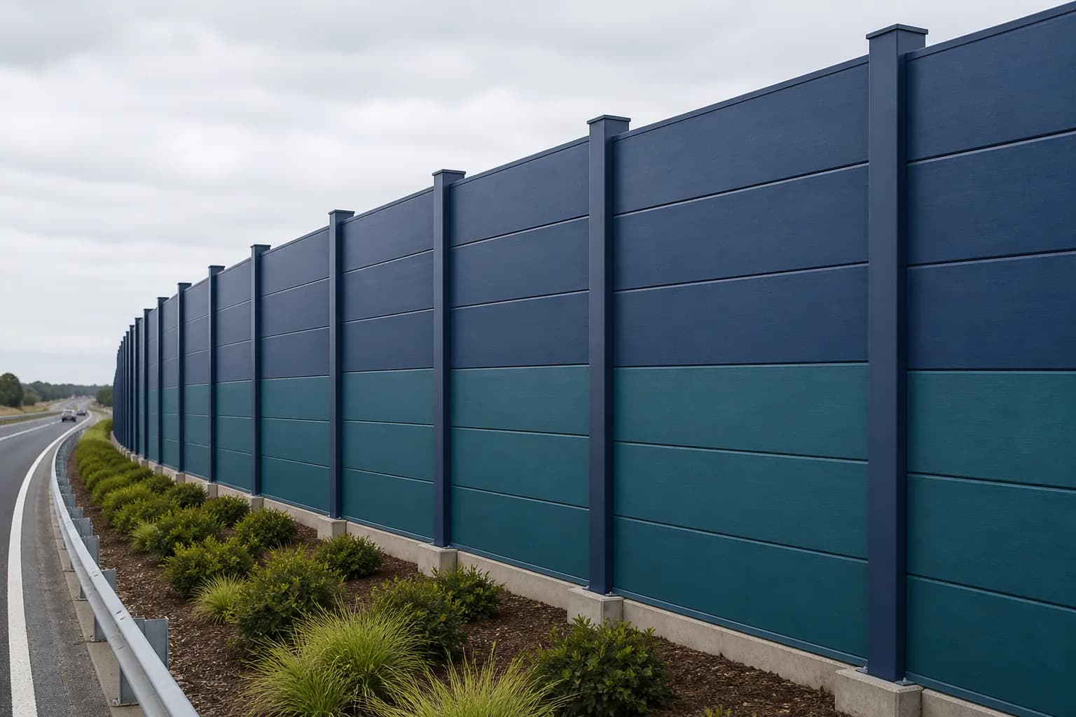
Blue and teal modular FRP sound barrier wall panels installed along a highway
AI-generated application visualization for concept planning. It is not an F1 project photograph, an approved shop drawing or evidence of a tested acoustic assembly.

2

reflective or absorptive configurations

1 system

panels, posts and closures coordinated with project foundation interfaces

Assembly-specific

acoustic evidence and structural calculations tied to the offered build-up

Drawing-led

dimensions and interfaces released before production

How Outdoor Barriers Work

Height, length and continuity set the installed result

A sound wall reduces the direct path from source to receiver. Sound still diffracts over the top and around the ends, which is why a strong panel can underperform when the wall is too short, too low or interrupted by unsealed gaps.

The U.S. Federal Highway Administration gives two useful planning rules: just blocking the line of sight commonly produces about 5 dB(A) insertion loss, while an effective design can approach 10 dB(A), perceived roughly as half as loud for the first row of receivers. Those are geometry-based highway rules of thumb, not guaranteed F1 panel values.

Read the FHWA acoustic-design basis ↗
Reflective & Absorptive Options

Two FRP noise barrier configurations, each released by assembly

The configuration follows the acoustic study. Competitor test values do not transfer to an F1 wall simply because both use pultruded fiberglass or a tongue-and-groove joint.

Reflective noise barrier · composite sound wall

Reflective FRP sound barrier panels

Closed pultruded FRP planks form a continuous barrier between posts. Interlocking edges, perimeter closures and seals control open paths through the wall.

Best fit

Projects where transmission control and a corrosion-resistant outdoor barrier are required, and reflected sound is acceptable in the acoustic model. Maintenance still depends on the resin, finish, seals, fasteners and exposure.

Release boundary

A hollow or closed panel is not assigned an STC, OITC or transmission-loss value until the offered wall specimen or panel build-up is traceable to applicable test evidence. Posts, closures and site gaps are checked separately because they affect installed leakage.

Absorptive noise barrier · outdoor acoustic barrier

Absorptive FRP noise barrier panels

A source-side acoustically open face and protected porous infill may be combined with a solid composite back. A declared NRC requires the offered perforation, core, facing, weather protection and mounting to match applicable test evidence.

Best fit

Parallel barriers, confined corridors, equipment yards and other layouts where the acoustic study calls for source-side absorption rather than reflection alone.

Release boundary

NRC is assembly-specific. Core type, thickness, facing, drainage and test orientation must match the cited laboratory report; a generic FRP skin has no automatic NRC value.

Custom Manufacturing & Supply

FRP sound barrier panel manufacturing and export supply

Move from wall geometry to a controlled pultrusion and shipment package. F1 separates project-specific engineering, test evidence and commercial release so the buyer can see exactly what is included before tooling or production begins.

Section review and custom pultrusion

F1 reviews the plank section, interlock, resin, reinforcement, color and finish against the wall geometry. A custom die and first article are quoted when an existing section cannot meet the released requirements.

QA and approval submittals

The order can define controlled drawings, dimensional checks, material records, finish samples and the acoustic evidence applicable to the offered specimen or panel build-up. Project acceptance remains with the named authority.

Commercial and export release

The quotation states tooling, sample plan, MOQ, production lead time, cut lengths, packing concept, Incoterm and destination. These items are confirmed for the project rather than presented as universal stock terms.

Review F1 factory-direct pultrusion controls →
Interlocking pultruded FRP sound barrier plank sections stacked between posts
Supplier reference rendering from Fibergrate illustrating one proprietary interlocking-plank concept. It is not an F1 project image or released F1 section; project geometry, joints and acoustic build-up must follow the approved drawings.
Complete Wall Assembly

FRP sound barrier panel installation and system components

A quote-ready system coordinates the pultruded planks with posts, seals, closures, finishes, anchors and foundation interfaces. This keeps the acoustic model, structural load path and installation sequence aligned through the same release drawing.

01

Interlocking wall planks

Horizontal pultruded fiberglass planks create the visible barrier surface. Tongue-and-groove or another sealed joint is developed around the chosen wall height, support spacing and acoustic configuration.

02

Posts and panel interfaces

FRP, galvanized-steel or other engineered posts transfer wind and environmental loads to the foundation. The post slot, bearing allowance and closure detail must preserve both structural support and acoustic continuity.

03

Base, top and end closures

Sound can leak through gaps that look minor on a general arrangement. Bottom seals, cap rails, end returns, penetrations and transitions are detailed as part of the wall, not left to site improvisation.

04

Optional absorptive build-up

When the acoustic model requires absorption, the source-side face, porous core, water management and protective layers are released together. Substituting one layer can invalidate the tested result.

05

Finish and environmental package

Integral pigment, surface veil and optional coating are selected from UV exposure, chemical contact, temperature, cleaning, graffiti-removal and visual requirements. Color approval follows a project sample.

06

Foundations and anchorage

Footings, base plates, anchor cages or embedded posts depend on soil, overturning, drainage, utilities and roadside clear-zone requirements. They are civil and structural design items, not catalog accessories.

Outdoor post-and-panel wall with horizontal infill panels at a commercial site
User-supplied layout reference showing a post-and-panel wall form that may inform a sound-wall configuration. The pictured product's material, function and project ownership are unverified; it is not an F1 project photograph or acoustic-performance evidence.
Plate Profile Application Path

Can fiberglass plate profiles become FRP sound-wall panels?

Some hollow or multi-cell pultruded plate sections can be evaluated as horizontal sound-wall planks when their cavity, return, edge and joint geometry fit the assembly. This is an application route, not a catalog equivalence: the section, laminate, sealed joints, post interface, loads and any absorptive build-up must be released together.

A plate drawing alone has no automatic NRC, STC, OITC, transmission-loss value or project span. Start with the section geometry, then complete the acoustic and structural review.

Compare hollow and multi-cell fiberglass plate profile drawings →
Acoustic Metrics

NRC, STC, OITC and insertion loss answer different questions

Do not convert one number into another or use a laboratory panel rating as a guaranteed property-line result. The test report, specimen construction and site model must agree.

MetricWhat it answersWhat it does not answer
NRCSingle-number laboratory absorption rating calculated from coefficients at 250, 500, 1000 and 2000 Hz for the stated specimen and mounting.The dB reduction at a home, property line or machine operator position.
STCSingle-number classification derived from laboratory transmission loss; primarily suited to speech and building-frequency comparisons.Installed outdoor insertion loss after diffraction, leakage and the actual source spectrum are considered.
OITCSingle-number classification using an outdoor reference spectrum with stronger low-frequency weighting.Installed outdoor insertion loss after diffraction, leakage and project geometry are considered.
Transmission lossFrequency-by-frequency reduction in airborne sound power transmitted through the tested specimen.Whether the wall is tall, long or continuous enough for the actual receiver geometry.
Insertion lossDifference in measured or predicted sound level at a defined receiver before and after installing the barrier under comparable source and environmental conditions.A transferable product rating independent of site, source, terrain and measurement conditions.
Material Decision

FRP vs concrete, steel and wood sound walls

FRP is not the automatic winner on every site. Its strongest cases combine constrained installation access with corrosive exposure, modular repair or a need to avoid metallic panels. Concrete remains compelling for mass and noncombustibility.

DecisionPultruded FRPConcreteSteel or wood
Handling and accessLow-density modular planks can reduce individual lift weight; the released panel length and lift plan still govern.High mass commonly needs heavy lifting and substantial foundations.Steel panels can be lighter than concrete; timber is easy to handle but section and treatment vary.
Corrosion and moistureNo metallic rust; resin, veil, finish, seals and fasteners must match UV, chemicals and temperature.The cementitious matrix does not rust, but reinforcement corrosion can follow cracking, chloride ingress or inadequate cover.Steel relies on coating integrity; timber relies on species, treatment, drainage and detailing.
Acoustic evidenceReflective and absorptive assemblies are possible. Only the offered tested build-up carries a declared rating.High mass supports transmission control, but site performance still depends on geometry and openings.Panel mass, joints, cavities and absorptive layers decide performance—not the material label alone.
Fire and impactResin, laminate, finish and the actual test specimen govern reported fire and impact performance; FRP is not noncombustible by default.Noncombustible and high-mass, with impact and reinforcement detailing checked to the project.Steel is noncombustible but loses strength with heat; timber needs a stated fire strategy and classification.
Modification and replacementModular bays can be removed without hot work when the connection detail allows it. Cutting requires dust control and edge sealing.Panel replacement normally has heavier lifting and traffic-management demands.Steel may require hot-work controls; timber is easy to cut but needs treatment at new edges.
From Noise Study to Release

Six inputs for an engineered FRP sound wall

Step 01

Acoustic design basis

Provide the noise source, operating spectrum, source height, receiver locations, existing levels, target criterion and the acoustic model. State whether the specification requires absorption, transmission loss, insertion loss or a combination.

Step 02

Wall geometry

Issue the alignment, total length, finished height, steps, returns, corners, gates, openings and ground profile. Height and continuity often control performance more than the panel material name.

Step 03

Structural actions

State governing wind, seismic, snow or ice, impact, fatigue and deflection criteria. Support spacing and plank section are released from calculations for the complete wall bay.

Step 04

Civil and roadside constraints

Identify soil report, drainage, slope, buried services, foundation limits, vehicle clear zone, crash barrier interface, maintenance access and installation staging.

Step 05

Environment and fire

List UV exposure, freeze/thaw, moisture, chemicals, temperature, cleaning and the exact fire test or classification required. ‘Weather resistant’ and ‘fire retardant’ are not complete acceptance criteria.

Step 06

Submittal and verification

Define required drawings, calculations, material data, acoustic test reports, finish samples, inspection records and jurisdictional approvals before production release.

Applications

Highway, railway, industrial and utility noise barriers

Highways and municipal corridors

Roadside walls where low panel mass, corrosion resistance and modular replacement can simplify access-constrained construction. Highway-agency acceptance remains jurisdiction- and project-specific.

Rail and transit

Trackside and station-edge noise control with the wall geometry coordinated around electrification, vibration, maintenance clearance and rail-authority requirements.

Industrial plants and mines

Perimeter or source-adjacent barriers around process equipment, compressors, conveyors and material-handling areas exposed to corrosive air and washdown.

Data centers and utilities

Outdoor enclosures for generators, transformers, cooling equipment and substations, with airflow, access, fire separation and electrical clearances designed alongside acoustics.

Commercial and logistics sites

Loading docks, drive-through lanes, rooftop equipment and property-line walls where appearance, maintenance access and neighboring receivers all matter.

Coastal and chemical environments

Composite sound walls for salt, humidity or chemical exposure where the resin, veil, finish, fasteners and support materials are selected from the actual service conditions.

Evidence and release boundary

Public references explain the design method—not F1 product ratings

The sources below define acoustic concepts, highway design expectations and test scopes. Supplier-specific NRC, STC, dimensions, spans and fire results are intentionally excluded from F1 claims unless the offered configuration is traceable to the same report and authorized for use. The released quotation and submittal control the actual product.

Have a question about this product?

Our FRP Engineering Advisor answers spec, sizing, and chemical-compatibility questions instantly — and routes complex ones to the right human.

Pre-filled question: “I need an FRP sound barrier wall: application [highway/railway/industrial/data center], source and operating spectrum [attach study if available], wall alignment/length/height [mm], receiver locations [describe], reflective or absorptive requirement [state], wind and governing code [state], soil/foundation information [state], fire/environment criteria [state], openings and access [describe], finish/color [state], quantity and destination [state]. Build the RFQ checklist and separate laboratory panel ratings from predicted field insertion loss.

Ask the AI advisor →

Frequently Asked Questions

What is an FRP sound barrier wall?

An FRP sound barrier wall is an outdoor noise-control system. In this application, the barrier planks are glass-fiber-reinforced polymer (GFRP), commonly called fiberglass or GRP; FRP is the broader composite-material family. Pultruded panels can stack between posts, with joints and perimeter closures detailed to limit acoustic leakage. The complete wall—not the panel skin alone—must be engineered for acoustics, wind, foundation interfaces, exposure and project approvals.

How do fiberglass noise barrier panels reduce sound?

A continuous wall blocks the direct path between a source and receiver, forcing sound to travel over the top or around the ends. A reflective assembly primarily limits transmission through the wall; an absorptive assembly also dissipates part of the incident sound at the source-side face. Height, length, location, sealed joints and surrounding geometry strongly affect the installed result.

What is the difference between reflective and absorptive FRP noise barriers?

A reflective barrier uses a closed surface and returns much of the incident sound toward the source side. An absorptive barrier may add an acoustically open source-side face and protected porous core to reduce reflection; a declared NRC requires the offered build-up and mounting to match applicable test evidence. Absorption can matter between parallel walls or in confined equipment areas, but it should be selected by the acoustic study rather than added as a generic upgrade.

What NRC, STC or noise-reduction rating does the F1 wall have?

F1 does not publish one generic rating for every configuration. NRC applies to the absorptive specimen and mounting tested. STC, OITC and transmission loss apply to the tested wall specimen or panel build-up. Posts, closures and site gaps still affect installed leakage and insertion loss. The quotation identifies the offered construction and the evidence that applies to it. Field insertion loss is predicted from the project geometry and verified only when the specification requires it.

Are FRP sound barrier walls approved by AASHTO or a DOT?

There is no universal approval that covers every highway agency and wall layout. The highway authority may require product acceptance, laboratory acoustic data, structural calculations, fire and durability evidence, and crash testing or shielding when the wall is in a roadside recovery zone. Acceptance should be checked against the named jurisdiction in a project compliance matrix; a general marketing claim does not substitute for agency acceptance.

Is an FRP noise barrier better than concrete, steel or wood?

FRP is attractive where low panel mass, corrosion resistance, electrical behavior or modular replacement reduce project risk. Concrete can still be the best high-mass, noncombustible option; steel can suit standardized metal-panel supply; timber can be economical and visually familiar. Compare the tested acoustic assembly, foundations, fire strategy, access, exposure and lifecycle maintenance rather than choosing by material name alone.

Which sizes, colors and resin systems are available?

Panel height, wall thickness, length, post spacing, color, finish and resin system are released against the project specification and manufacturing review. F1 can evaluate integral colors, surface veils, coatings, reflective or absorptive faces, and container-compatible delivery lengths. Public competitor dimensions are not presented as F1 stock sizes.

What information is needed for an FRP sound barrier quote?

Send the noise study or source data, alignment, total length and height, receiver locations, reflective or absorptive requirement, wind and other structural actions, soil and foundation information, fire and environmental criteria, color, openings, jurisdiction, drawings, quantity, destination and required delivery date. A marked plan and elevation are the fastest starting point.

How are FRP sound barrier panels installed?

Installation normally follows the released sequence for foundations or anchor interfaces, posts, bearing details, stacked or inserted planks, seals and top/end closures. The installer must protect joint continuity, stated bearing, thermal movement and panel finish; gates, penetrations, steps and damaged cut edges need the project detail. Lift weights, temporary bracing, traffic control and dust controls are confirmed in the site method statement.
Send the noise study and wall alignment for engineering review

Send the dimensions, quantity, service environment, and destination. Engineering responds within one business day.