
Load path
Bidirectional molded reinforcement
Square-mesh panels can be oriented or field-cut without creating a single pultrusion load direction.
Molded fiberglass grating in square mesh, mini mesh and rectangular mesh configurations — with manual-verified panel sizes, nominal weights, open area and matched M/C/J installation clips.
Send the dimensions, quantity, service environment, and destination for a scoped response.

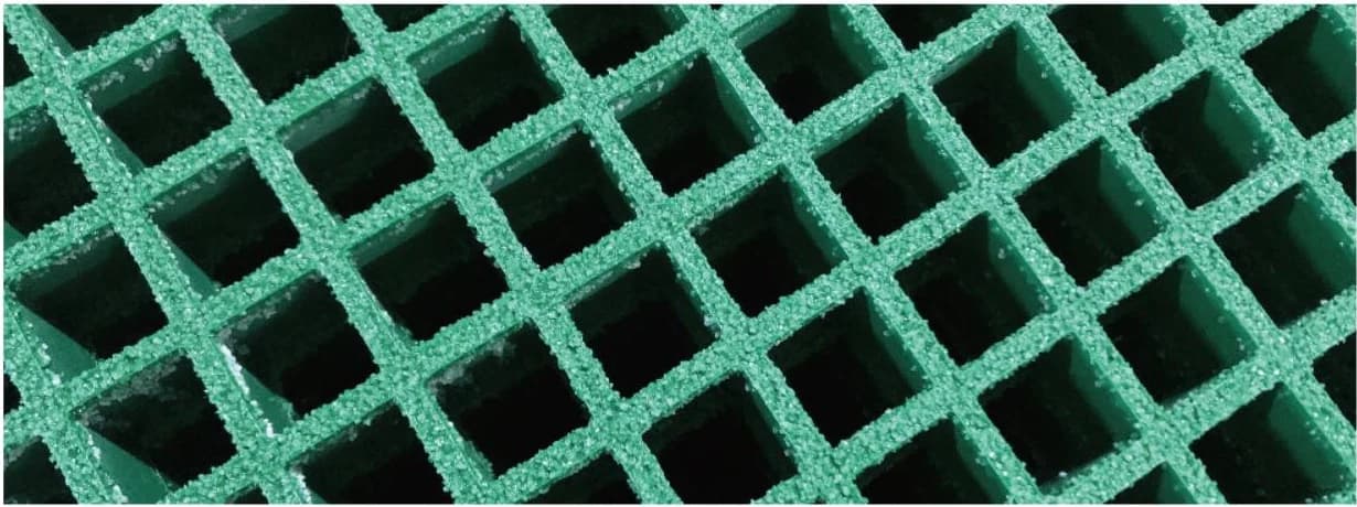
Molded fiberglass grating is cured as one panel with glass reinforcement running in both directions. It is the F1-GRID choice when the layout contains frequent penetrations, loads can approach from more than one direction, or the project needs resin-rich corrosion performance with a wide choice of square and mini meshes.
The supplied manual describes interlaced glass roving in a polyester-resin mold, thermally cured to a finished panel with 30–35% glass content by total weight. Its fire-retardant formulation is described as ASTM E84 Class 1 with a flame-spread index of 25 or less. Those are catalog construction references; the resin, fire report and batch documentation named in the F1 order govern the delivered product.

Load path
Square-mesh panels can be oriented or field-cut without creating a single pultrusion load direction.
Catalog depth range
Standard and high-depth rows are listed by mesh, bar thickness, panel format, nominal weight and open area.
Catalog glass content
The supplied manual describes interlaced glass roving thermally cured in a resin-filled mold.
Walking surfaces
Select the opening and surface against drainage, heel resistance, slip, cleaning and project access rules.
The matrix below transcribes the principal square-mesh and mini-mesh production rows from the supplied molded-grating manual. Dimensions are millimeters; weight is nominal kg/m². Use these values to shortlist tooling, then obtain the F1 quotation, certified datasheet and approved panel-layout drawing for the project release.
Standard industrial square mesh; HD rows are high-depth configurations.
| Depth (mm) | Bar top / bottom (mm) | Standard panel sizes (mm) | Weight (kg/m²) | Open area |
|---|---|---|---|---|
| 13 | 6.0 / 5.0 | 1524 × 4000; 1220 × 3660; 1220 × 2440; 921 × 3050 | 6.1 | 78% |
| 15 | 6.0 / 5.0 | 1524 × 4000; 1220 × 3660; 1220 × 2440; 921 × 3050 | 7.1 | 78% |
| 20 | 6.5 / 5.0 | 1524 × 4000; 1220 × 3660; 1220 × 2440; 921 × 3050 | 9.6 | 68% |
| 25 | 6.5 / 5.0 | 1524 × 4000; 1220 × 3660; 1220 × 2440; 921 × 3050 | 12.3 | 68% |
| 30 | 6.5 / 5.0 | 1524 × 4000; 1220 × 3660; 1220 × 2440; 921 × 3050 | 14.6 | 68% |
| 38 | 7.0 / 5.0 | 1524 × 4000; 1220 × 3660; 1220 × 2440; 921 × 3050 | 19.5 | 68% |
| 40 | 7.0 / 5.0 | 1524 × 4000; 1220 × 3660; 1220 × 2440; 921 × 3050 | 20.6 | 68% |
| 50 (HD) | 9.5 / 7.5 | 1220 × 3660; 1220 × 2440; 921 × 3050 | 40.0 | 56% |
| 60 (HD) | 10.5 / 8.5 | 1220 × 3660; 1220 × 2440; 921 × 3050 | 48.0 | 54% |
| 65 (HD) | 11.0 / 9.0 | 1220 × 3660; 1220 × 2440; 921 × 3050 | 52.0 | 52% |
| Depth (mm) | Bar top / bottom (mm) | Standard panel sizes (mm) | Weight (kg/m²) | Open area |
|---|---|---|---|---|
| 25 | 7.0 / 5.0 | 1007 × 3007; 1007 × 4007; 1247 × 3687; 1527 × 4047 | 12.3 | 67% |
| 30 | 7.0 / 5.0 | 1007 × 3007; 1007 × 4007; 1247 × 3687; 1527 × 4047 | 14.5 | 67% |
| 40 | 7.0 / 5.0 | 1007 × 3007; 1007 × 4007; 967 × 2967; 1527 × 4047 | 19.2 | 67% |
| Depth (mm) | Bar top / bottom (mm) | Standard panel sizes (mm) | Weight (kg/m²) | Open area |
|---|---|---|---|---|
| 13 | 6.0 / 5.0 | 1524 × 4000; 1220 × 3660; 1220 × 2440; 921 × 3050 | 5.8 | 82% |
| 15 | 7.0 / 6.0 | 1524 × 4000; 1220 × 3660; 1220 × 2440; 921 × 3050 | 6.8 | 82% |
| 25 | 7.5 / 6.0 | 1220 × 3660; 1220 × 2440 | 11.8 | 78% |
| 40 | 7.0 / 5.0 | 1788 × 4531; 1220 × 3660; 1220 × 2440; 921 × 3050 | 17.8 | 78% |
| 50 | 7.5 / 5.0 | 1524 × 4000; 1220 × 3660; 1220 × 2440; 921 × 3050 | 21.5 | 78% |
| 50 | 8.0 / 6.0 | 1524 × 4000; 1220 × 3660; 1220 × 2440; 921 × 3050 | 23.5 | 78% |
| Depth (mm) | Bar top / bottom (mm) | Standard panel sizes (mm) | Weight (kg/m²) | Open area |
|---|---|---|---|---|
| 25 | 7.0 / 5.0 | 1007 × 4007; 1173 × 4007 | 6.1 | 84% |
| 40 | 7.0 / 5.0 | 1007 × 4007; 1173 × 4007 | 9.6 | 84% |
Small top opening for pedestrian and heel-resistant layouts; verify the governing accessibility requirement.
| Depth (mm) | Bar top / bottom (mm) | Standard panel sizes (mm) | Weight (kg/m²) | Open area |
|---|---|---|---|---|
| 25 | 6.5 / 5.0 | 1524 × 4000; 1220 × 3660; 1220 × 2440; 921 × 3050 | 16.8 | 30% |
| 30 | 6.5 / 5.0 | 1524 × 4000; 1220 × 3660; 1220 × 2440; 921 × 3050 | 18.5 | 30% |
| 38 | 6.5 / 5.0 | 1220 × 3660; 1220 × 2440; 921 × 3050 | 23.5 | 30% |
| Depth (mm) | Bar top / bottom (mm) | Standard panel sizes (mm) | Weight (kg/m²) | Open area |
|---|---|---|---|---|
| 15 | 6.5 / 5.0 | 1220 × 3660; 1220 × 2440; 921 × 3050 | 7.5 | 55% |
| 50 | 8.0 / 6.0 | 1524 × 4000; 1220 × 3660; 1220 × 2440; 921 × 3050 | 28.5 | 55% |
These additional molds appear in the supplied manual. Request the exact row and project load table before specifying.
20 × 20 / 40 × 40 mm mini mesh
Catalog depths: 14, 22, 30, 40, 60 mm
26 × 26 / 52 × 52 mm mini mesh
Catalog depths: 30, 38 mm
13 × 13 / 40 × 40 mm mini mesh
Catalog depths: 22, 30, 40 mm
25 × 100 mm rectangular mesh
Catalog depths: 25, 30 mm
25.4 × 101.6 mm rectangular mesh
Catalog depths: 25, 25 HD, 38 mm
38.1 × 101.6 mm rectangular mesh
Catalog depths: 38, 50 mm
25.4 × 152.4 mm rectangular mesh
Catalog depths: 38 mm
38.1 × 152.4 mm rectangular mesh
Catalog depths: 38 mm
25.4 × 50.8 mm rectangular mesh
Catalog depths: 38, 50 mm
60 × 100 mm rectangular mesh
Catalog depths: 28 mm
60 × 220 mm rectangular mesh
Catalog depths: 40 mm
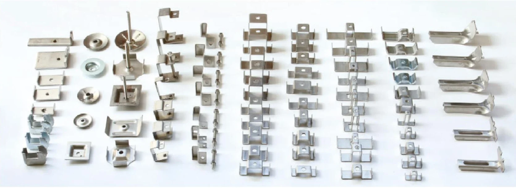
The catalog hardware photograph shows the wider grating-fastener family. For this molded-grating page, F1 publishes only the applicable M hold-down, C panel connector and J support-hook functions below. The photograph is a visual reference, not a promise that every pictured geometry is a stocked F1 SKU.

F1 molded-grating clip kits separate panel hold-downs from panel-edge connectors. Select the hardware from the mesh, panel depth, support detail and installation access, then issue the exact assembly on the approved panel-layout drawing. The diagrams explain compatibility and load path only — they are not fabrication dimensions.
M, C, and J are F1-GRID molded-grating product definitions. A C connector joins compatible molded-panel edges but does not replace support or each panel's independent hold-downs.
F1-GRID clip M
Seats across two adjacent grating bars to hold an open-mesh panel to its supporting member.
Boundary: Panel depth, bar profile, support geometry, and access determine the final hardware arrangement.
F1-GRID clip C
Connects adjacent molded-grating panel edges to control relative movement and maintain alignment at the joint.
Boundary: A C connector is not structural support and is not a panel-to-support hold-down. Each panel must remain independently supported and secured.
F1-GRID clip J
Pairs a lower J hook with an approved upper clip and fastener to clamp the panel to a support flange without drilling the support frame.
Boundary: The J hook and upper clip are not universal; the approved drawing must match the grating opening, support flange, fastener, and installation access.
General coordination values before project-specific fastening design.
These are general starting coordination values, not a final fastening design. The approved project drawing, project engineer, grating series, support condition, and applicable manufacturer requirements control the final layout.
Combined CAD detail
One family-specific DXF containing the M/C/J typical installation details and F1 SKU references. Project-specific geometry remains governed by the approved project drawing.
Download M/C/J DXFFree DXF · no login · verify revision before issue for construction
Final clip geometry, bolt and washer selection, quantity, spacing, edge clearances, and tightening requirements must be shown on the approved project drawing. The clip guide does not change the grating span, bearing, support, or connection design checks.
Separate product family
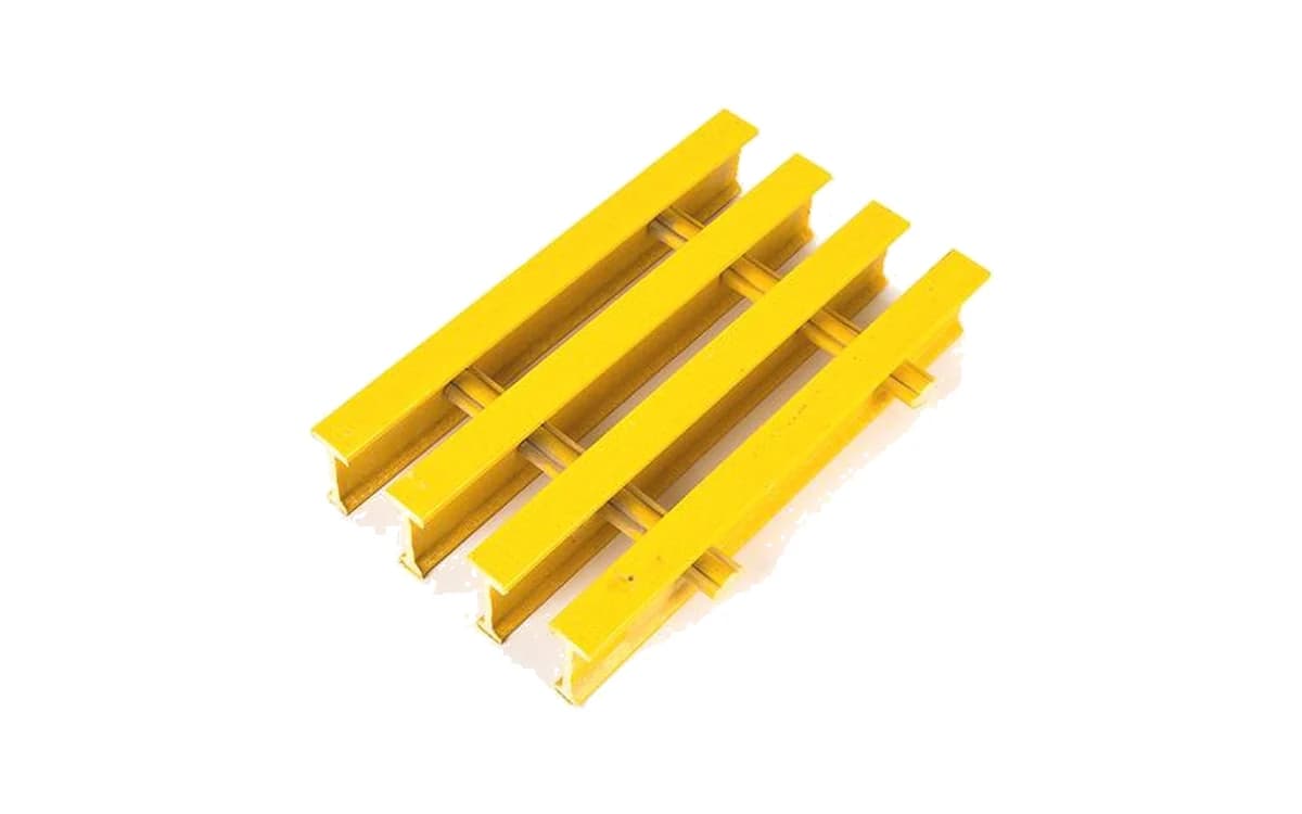
Pultruded grating now has its own page, specification table and M/J/T clip selection so its bearing-bar data is not mixed with molded mesh.
Molded FRP grating is a one-piece panel made by placing continuous glass-fiber reinforcement in both directions of a mold and curing it in a resin matrix. That two-way architecture is the key difference from pultruded grating, whose bearing bars primarily carry load in one direction.
Use 38.1 × 38.1 mm or 40 × 40 mm square mesh for general industrial platforms; 50.8 × 50.8 mm or 83 × 83 mm when higher open area is important; and mini-mesh configurations when the top opening must be reduced for pedestrian access. The final choice must also satisfy the required load table, support spacing, drainage, slip resistance and local accessibility rules.
They are nominal production-catalog values transcribed from the supplied molded-grating manual. Use them for product selection and logistics planning. The F1 quotation, approved panel-layout drawing and order-specific certified datasheet control final dimensions, tolerances, resin, surface, load capacity and delivered weight.
Yes. Its bidirectional reinforcement makes molded grating well suited to field cutouts and irregular layouts. Every cut still needs adequate bearing and cut-edge support; seal exposed cut surfaces with a compatible resin and re-check the hold-down layout on the approved installation drawing.
F1 uses M hold-down clips for compatible panel-to-support connections, C connectors between adjacent molded-panel edges, and J support-hook assemblies where the approved detail clamps around a support flange without drilling it. C clips do not replace structural support or each panel's independent hold-downs.
Yes. The F1 M/C/J clip kits shown here are specified in 316 stainless steel. Clip geometry, bolt length, complete fastener assembly, quantity and spacing are selected against the panel depth, mesh, support flange and installation access, then issued on the approved project drawing.
Choose pultruded FRP grating when the design is governed by longer one-way spans, higher stiffness in the bearing-bar direction, dedicated I-bar or T-bar series, or structural deck-panel options. Use the separate pultruded FRP grating page so its bearing-bar data and M/J/T clips are not mixed with molded mesh specifications.
Our FRP Engineering Advisor answers spec, sizing, and chemical-compatibility questions instantly — and routes complex ones to the right human.
Pre-filled question: “I need molded FRP grating for [application]. Mesh/depth [mm], panel quantity or layout [details], clear support spacing [mm], design load [kN/m² or point load], resin/chemical exposure [details], surface [concave/fine grit/coarse grit], support flange and underside access [details]. Please confirm the catalog row, M/C/J 316SS clips, panel layout and required approval documents.”
Send the dimensions, quantity, service environment, and destination. Engineering responds within one business day.