Straight line, modest line angle
Tangent distribution pole
Define vertical conductor and ice loads, wind loads, insulator positions and the pole-center attachment. Verify the full member-and-mount arrangement.
Plan a fiberglass crossarm around the complete pole assembly. Start with conductor arrangement, structural actions and electrical clearances, then define the profile, holes, brackets, insulators and evidence required by the utility.
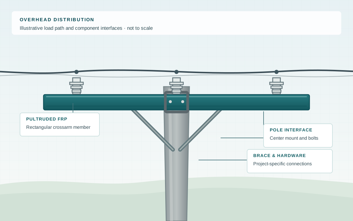
Straight line, modest line angle
Define vertical conductor and ice loads, wind loads, insulator positions and the pole-center attachment. Verify the full member-and-mount arrangement.
Line changes direction or terminates
Longitudinal and transverse forces can control. Specify guying, brace and mount details, then qualify the complete assembly for the utility's load cases.
Existing wood or steel crossarms
Survey pole spacing, insulator hardware, holes and clearances. A matching length or section depth alone does not establish structural or electrical equivalence.
Glass FRP can avoid timber rot and steel rust in compatible outdoor service. Actual durability depends on the resin, surface protection, end details and installed environment. Explore energy applications.
01 · member
Confirm outer section, wall thickness, length, laminate and surface system against available tooling and the utility drawing. Hollow rectangular sections are one common arrangement, not a fixed F1 size range.
02 · interfaces
Schedule insulator and pole-clamp holes, edge distances, inserts or local reinforcement, cut-end sealing and end caps where required by the accepted design.
03 · hardware
Identify center mount, pole bolts, braces, insulator fittings and corrosion protection. Metal hardware remains part of the electrical and corrosion assessment.
04 · scope
Request a raw profile, cut-and-drilled member or agreed component package. Factory fabrication, mounts, hardware, testing and engineering deliverables are listed explicitly in the quotation.
Check 01
Provide conductor type and span, self-weight, ice, wind, line angle and any broken-wire or construction cases required by the owner. State load combinations and the allowable deflection.
Check 02
Check both bending directions, shear, long-duration behavior and local compression at pole mounts, braces and insulator holes. Hole pattern and edge distance affect capacity.
Check 03
The electrical designer sets voltage class, insulation coordination, air and surface clearances, creepage, bonding and lightning protection. A glass FRP member is not a substitute for an approved insulator assembly.
Check 04
Specify UV protection, wet-contamination tracking performance, moisture ingress control and cut-edge or drilled-hole sealing for the actual exposure.
| Reference | Scope | Request with RFQ |
|---|---|---|
| ASTM D8019 | Full-section flexural modulus and bending strength of assembled tangent and dead-end FRP crossarms with center mounts. | Test configuration, span, holes, loading directions, failure mode and result for the offered assembly. |
| ASTM D2303 | Relative tracking and erosion resistance of an insulating material under liquid contamination. | Report for the specified laminate or surface system, including specimen and test conditions. |
| ASTM G154 | Controlled fluorescent UV and moisture exposure procedure; it does not itself set a pass/fail service life. | Exposure cycle, duration and retained property or surface evaluation criteria. |
| Utility / local line code | Site loading, clearances, construction and acceptance requirements are set by the owner and jurisdiction. | Applicable drawing, code edition, inspection plan and approval responsibility. |
Voltage class, tangent / angle / dead-end duty, pole type, conductor and insulator layout, required clearances.
Design loads and combinations, deflection criteria, member size and length, hole coordinates, mounts and braces.
Required test reports, surface and end treatment, inspection and marking, supply scope, quantity and destination.
Reference designs from other manufacturers are useful for defining questions, but their load ratings, voltage suitability and service-life statements do not transfer to an F1 offer.
It can be developed for a replacement arrangement, but the pole mount, hole pattern, insulator positions, load cases and electrical clearances must be checked together. A matching outer dimension is only a starting point.
There is no universal voltage rating from the material name or crossarm shape. Insulation coordination depends on the complete line geometry, insulators, contamination, clearances and tests required by the utility.
They may use similar composite materials, but transmission members can have much larger spans, forces and connection systems. This page describes distribution planning; transmission or H-frame work needs a separate engineering and qualification scope.
Only if the approved design and supplier procedure permit them. Added holes can change bending capacity and local bearing, and freshly exposed laminate requires the specified sealing treatment.
A utility drawing or sketch, pole configuration, voltage class, load schedule, crossarm dimensions and hole plan, material and test requirements, quantity and destination. The initial enquiry can be sent before every detail is final.
Start with the pole drawing or a sketch, the supply scope you need and the project location. Loads and test criteria can follow if they are still being finalized. We reply within one business day; a formal quotation follows once the specification and delivery are reviewed.