Skip to content
Pultrusion application guide

CFRP beams and struts for industrial robots

Lower moving mass can help a robot or handling gantry only when the complete member remains stiff, dimensionally stable and securely connected through its operating cycle. Specify the beam, end joints and machine response together.

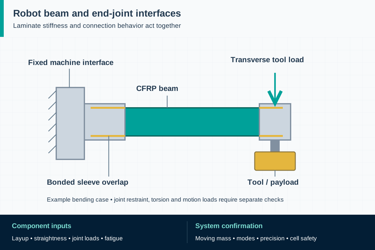
FIG. 1 CFRP robotic beams and strutsApplication schematic · not to scale
One cantilever bending case: follow the load from the tool adapter through the beam and bonded sleeve to the fixed machine root. Torsion and dynamic cases require separate checks.

Component scope and material selection

F1 can review a component qualification inquiry for a constant-section carbon profile against an OEM specification. Finished robot arms, precision end fittings, bonded assemblies and machine validation require an agreed scope and evidence before any supply commitment.

Select the complete material system

Carbon-fiber thermoset profiles with an architecture selected for axial, bending, transverse and torsional loads; any added reinforcement or hybrid manufacture must be specified.

Components to specify

  • Closed rectangular beams for moving gantries
  • Round or shaped tubes for parallel robot links
  • Constant-section strut bodies with separately engineered end interfaces

Begin with the motion and accuracy requirement

Define what the moving structure carries: payload, gripper, cables, hoses, sensors and fixtures. Include their positions, not only their combined mass. Give the mechanical designer the motion envelope, acceleration and deceleration history, stopping events, duty cycle and allowable disturbance at the tool center. A lighter tube offers little benefit if heavier adapters restore the removed mass or flexible interfaces dominate the motion.

Industry examples include delta-robot links, moving inspection gantries and automated handling frames. These are separate design problems: a mostly axial link differs from a transverse beam carrying an offset carriage. Write a measurable objective such as reduced settling time under a defined payload, then agree on how it will be assessed. Do not turn another supplier's advertised cycle rate into the design requirement for an unrelated machine.

ReferencesEpsilon Composite: carbon-fiber delta robot armsEpsilon Composite: carbon beams for industrial machinesISO 9283:1998: robot performance and testing

Separate beam stiffness from member stability

Map the forces from the payload through the beam or strut, connections and bearings into the supporting machine. For a beam, include bending about both axes and torsion from an eccentric carriage. For a compression link, evaluate global buckling, local wall instability and load eccentricity as well as material strength. A high longitudinal tensile modulus does not resolve all of these limit states.

Request direction-dependent properties for the proposed laminate rather than a single carbon-fiber modulus. A fiber grade describes a constituent; the cured profile also contains resin and reinforcement in other directions. Open sections can twist under loads that appear to be simple bending, and laminate architecture influences that response. The section model, restraint assumptions and allowable deflection should therefore appear in the review before a tool or prototype is ordered.

ReferencesNASA TP-3512: buckling of composite beamsEpsilon Composite: carbon beams for industrial machines

Choose a section that the process can produce

Continuous pultrusion is suited to a repeated cross-section. A local boss, a tapered wall or a curved transition requires a separate manufacturing decision. Consider whether a straight blank with engineered fittings is sufficient, or whether an additional winding, molding or lay-up operation is needed. Commercial beam programs use several of these routes; the presence of a pultruded element does not make the complete assembly a simple pultrusion.

The inquiry should distinguish material architecture, manufacturing process and delivered condition. For instance, a predominantly axial tube and a tube with additional off-axis reinforcement can share outer dimensions while responding differently to torque and clamp loads. Identify the necessary interface stiffness and load capacity first. Specify a hybrid process only when its benefit and qualification plan justify the added tooling, joints and production controls.

ReferencesEpsilon Composite: carbon beams for industrial machinesEpsilon Composite: standard-profile catalog

Engineer the end joints as part of the member

A strut must transfer load into a clevis, ball joint or machine bracket without pulling out its fitting, crushing its wall or splitting around a hole. Record joint-center distance, end-axis alignment, rotational orientation, bearing conditions and assembly access. Do not specify a metal bolt torque and assume the composite will tolerate the same clamping pressure. Sleeves, load-spreading faces or local reinforcement may be needed, subject to the actual joint design.

For a bonded fitting, agree on the overlap geometry, surface preparation, adhesive identity, bond-line control, cure record and inspection method with the responsible designer. Check tension, compression and load reversal, not just one pull test. Keep electrically conductive carbon isolated from incompatible metal contact where the exposure requires it, with a detail that survives wear and moisture. These are engineering review items; this guide supplies neither an adhesive recipe nor a universal joint allowable.
ReferencesNASA: bolted joints for pultruded carbon-epoxy reinforcementFAA AC 20-107B with Change 1: composite structural substantiationEpsilon Composite: standard-profile catalog

Validate accuracy with the assembled machine

Static deflection is only one part of positioning behavior. The complete structure has modes influenced by bearings, end fittings, actuators and the carried load. Ask whether a change in mass or stiffness affects the controller tuning, overshoot, settling and accuracy across the working envelope. A lighter beam can change the response; it does not guarantee a faster or more accurate production cycle without machine-level evidence.

Separate geometric acceptance of the member from performance acceptance of the robot. Measure relevant dimensions from functional datums after assembly, then assess selected motion characteristics with the agreed payload and operating conditions. Include a thermally stable reference condition and the expected operating state. Use ISO 9283 where appropriate to the robot-performance contract, while retaining application-specific tests for the actual picking, inspection or processing task.

ReferencesISO 9283:1998: robot performance and testingISO 10218-2:2025: robot applications and cells

Qualify repeated loading and credible damage

Translate the machine duty into a load spectrum for the member and joints. Reversal, start-stop operation, exceptional stops, temperature and cleaning exposure may affect different parts of the assembly. Establish which events are normal service and which require inspection or removal. An undamaged coupon result cannot determine the service life of a complete arm with fittings, holes and a possible handling impact.

Use a staged verification plan: establish material and process consistency, test representative interfaces, then test the assembled member and validate the machine. Agree on acceptance criteria before testing and document what configurations the results cover. The background composite literature supports this progression, but aviation factors and acceptance limits should not be imported into a robot contract. The OEM must choose the appropriate life, variability and residual-capacity requirements for its machinery.

ReferencesFAA AC 20-107B with Change 1: composite structural substantiationISO 12100:2010: machinery risk assessment

Treat a replacement arm as an engineering change

Industrial robot safety responsibilities sit with the robot manufacturer and system integrator. ISO 10218 distinguishes the robot from its application and cell; replacing a structural member can affect both. Review failure consequences, ejected parts, payload retention, access during recovery and whether the change affects protective functions or their assumptions. Reduced mass alone does not make a collaborative application safe.

For an EU project approaching the machinery-legislation transition, record the planned placing-on-the-market date and responsible conformity route. Use the current applicable requirements and adopted standards rather than assuming publication of a newer standard automatically changes every existing machine. Keep the component drawing, structural evidence and integration-validation records connected so that a later replacement can be assessed against the accepted configuration.

ReferencesISO 10218-1:2025: industrial robotsISO 10218-2:2025: robot applications and cellsEUR-Lex: machinery safety requirements and transition dates

Make inspection and replacement practical

Define accessible inspection locations before the beam is hidden by covers or cable carriers. The maintenance instructions should identify reportable surface damage, loose or displaced fittings, unexpected play and changes in positioning behavior. Specify who may assess a damaged member and which conditions stop service. A coat of paint or a local resin patch is not an established structural repair procedure.

Provide traceable part and revision identification without damaging critical fibers or bond areas. Keep the original qualification evidence, permitted modifications, replacement orientation and assembly instructions available to maintenance personnel. After an abnormal stop or collision, review the event against the OEM procedure rather than relying only on appearance. Production release should identify the exact drawing, material, process and joint configuration accepted by the customer.

ReferencesISO 12100:2010: machinery risk assessmentFAA AC 20-107B with Change 1: composite structural substantiation

Standards, regulations and acceptance evidence

The project authority determines the governing jurisdiction and adopted edition. The scope of each reference matters: a material test, an equipment requirement and a workplace rule answer different questions.

Standard · International machinery design; apply through the project conformity route

ISO 12100:2010

Risk assessment and risk reduction for the machine, including foreseeable misuse and life-cycle activities.

Application boundary: A low-mass beam is one design input. It does not establish the safety of motion controls, guarding or human access, and this standard supplies no generic CFRP allowable stress.

ReferencesISO 12100:2010: machinery risk assessment

Standard · Industrial robot and robot-cell programs adopting these standards

ISO 10218-1:2025 and ISO 10218-2:2025

Part 1 addresses industrial robots; Part 2 addresses integration, industrial robot applications and cells.

Application boundary: Not standalone profile certificates. The robot builder and integrator determine applicability and validation. Medical robots and lifting or transporting people are outside Part 1's scope; this page concerns industrial handling machinery.

ReferencesISO 10218-1:2025: industrial robotsISO 10218-2:2025: robot applications and cells

Standard · Industrial robot performance specifications where contractually adopted

ISO 9283:1998

Methods for specifying and testing robot performance characteristics, distinct from safety requirements.

Application boundary: The purchaser must select the relevant characteristics and acceptance conditions. A beam dimensional report does not establish the assembled robot's accuracy, repeatability or settling behavior.

ReferencesISO 9283:1998: robot performance and testing

Regulation · European Union; applicable machinery placed on the market or put into service

Regulation (EU) 2023/1230 (Machinery Regulation)

Determine the applicable route under Directive 2006/42/EC or Regulation (EU) 2023/1230 against the relevant date; the regulation generally applies from 20 January 2027.

Application boundary: Specified provisions apply earlier. A profile is not automatically machinery or a separately regulated safety component. The responsible manufacturer must determine the supplied item's role and the effect of a retrofit on conformity.

ReferencesEUR-Lex: machinery safety requirements and transition dates

Public source scopes were reviewed on . These references do not establish certification of an F1 product. Agree the offered grade, finished component, test specimen and acceptance criteria in the project specification.

CFRP robotic beams and struts: practical questions

Can a carbon tube replace a metal robot arm with the same dimensions?

Not without an engineering review. Direction-dependent stiffness, joint load transfer, stability, thermal behavior and machine response can differ. The accepted drawing and validation must address the complete member and its integration.

Does higher fiber modulus guarantee better robot accuracy?

No. Fiber modulus is a constituent property. Profile architecture, connection stiffness, geometry, drive behavior and operating temperature all contribute to the assembled machine's response.

Can F1 supply a ready-to-install robot arm?

This page supports a component qualification inquiry. End fittings, bonding, machining, metrology and assembled-member validation must be explicitly reviewed and accepted before a finished-arm supply scope can be confirmed.

Is a lightweight robot automatically safe for human collaboration?

No. The integrator must assess the complete application and hazards, including the tool, payload, motion and protective measures. Material selection does not replace that assessment. Collaborative-application requirements formerly in ISO/TS 15066:2016 are now part of ISO 10218-2:2025.

Technical sources and further reading

Industry sources establish where the application is used. Authority sources define the published scope of standards and regulations. The design and procurement checklists above are an original engineering synthesis for project review.
  1. Industry application evidence

    Epsilon Composite: carbon beams for industrial machines

    Application evidence for machine gantries and handling structures. Describes pultrusion as well as hybrid processes; its dimensions, tolerances and performance are not F1 specifications.

  2. Industry application evidence

    Epsilon Composite: carbon-fiber delta robot arms

    Documents tubes with assembled end fittings for delta robots. Published acceleration, cycle-rate and accuracy claims belong to that supplier and are not reproduced as design values.

  3. Industry application evidence

    Epsilon Composite: standard-profile catalog

    Distinguishes reinforcement/process variants and identifies a glass protective layer on a carbon profile. Not a catalog of F1 tooling or stock.

  4. Standard or public authority

    NASA TP-3512: buckling of composite beams

    Research on laminate architecture, shear-center position and twisting of open-section composite beams. Engineering background, not a robot design code or pultruded-product qualification.

  5. Standard or public authority

    NASA: bolted joints for pultruded carbon-epoxy reinforcement

    Experimental aerospace work illustrates that tension and compression load transfer require joint-specific analysis and testing. Its loads and allowables are not transferable to robot parts.

  6. Standard or public authority

    FAA AC 20-107B with Change 1: composite structural substantiation

    Background for staged composite testing, environmental effects, process control and damage. This aviation guidance is not a governing requirement for industrial robots.

  7. Standard or public authority

    ISO 12100:2010: machinery risk assessment

    Official publisher scope for machinery risk assessment and risk reduction throughout the machine life cycle.

  8. Standard or public authority

    ISO 10218-1:2025: industrial robots

    Current Part 1 addresses the industrial robot; excludes medical robots, lifting people and other stated uses. It does not certify a carbon component.

  9. Standard or public authority

    ISO 10218-2:2025: robot applications and cells

    Current Part 2 addresses integration into industrial robot applications and cells, rather than material properties.

  10. Standard or public authority

    ISO 9283:1998: robot performance and testing

    Publisher lists this edition as published/current. Robot performance testing is distinct from structural coupon testing and safety conformity.

  11. Standard or public authority

    EUR-Lex: machinery safety requirements and transition dates

    Official summary gives 20 January 2027 as the general application date of Regulation (EU) 2023/1230, with specified provisions applying earlier.

Prepare a component qualification brief

Provide the application and acceptance requirements so we can assess material, geometry, sampling and the proposed supply scope. We reply within one business day; a formal quotation follows once the specification and delivery are reviewed.

01 · Machine type, intended use, installation country and responsible OEM or integrator.
02 · Payload, moving accessories, load positions, motion history and expected operating life.
03 · Beam span or joint-center length, cross-section envelope, restraints and interface drawings.
04 · Direction-specific stiffness requirements, deflection limits, buckling and torsional load cases.
05 · Fitting materials, alignment datums, adhesive or mechanical joint scope and inspection access.
06 · Temperature, moisture, cleaning agents, impact exposure and conductive-material constraints.
07 · Component tests, selected machine-performance tests and agreed acceptance authority.
08 · Prototype quantity, expected production volume, traceability and change-notification requirements.
Get a quoteWhatsApp