Skip to content
Pultrusion application guide

FRP insulation supports for dry-type transformers

A winding support must maintain position, carry its assigned loads and preserve the cooling and insulation arrangement. Define those jobs together before selecting a dog-bone, channel, angle or custom pultruded section.

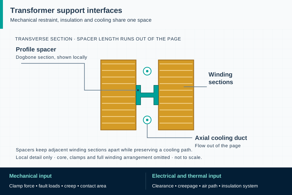
FIG. 1 Dry-type transformer insulation supportsApplication schematic · not to scale
The dogbone spacer separates adjacent winding sections. Its length and the cooling flow run out of the page; circle-dot symbols identify the axial ducts.

Component scope and material selection

Send a component drawing and equipment qualification requirements for feasibility review. This guide concerns pultruded support components; it does not establish an F1 thermal class, transformer approval or validated insulation system.

Select the complete material system

Glass-reinforced thermoset profiles with a project-qualified resin, reinforcement and surface system

Components to specify

  • Dog-bone winding spacers
  • Insulating channels and angles
  • Support strips and custom constant-section holders

Identify the support's job inside the transformer

Start with an annotated equipment section. Show the winding, core, clamps, grounded metalwork and cooling passages, then mark what each proposed FRP part must locate or support. An axial spacer, a radial positioning strip and a holder around a winding can require different stiffness, contact geometry and insulation arrangements even when their cross-sections look similar. Record the installation orientation so that loads can be related to the profile's fiber directions.

Pultrusion suits a repeating cross-section followed by controlled cutting and machining. Röchling's dry-transformer examples identify profile-based holders and dog-bone winding spacers; they also identify pressure blocks machined from sheet, which are a different product route. The following design questions are an engineering specification framework. They do not transfer that supplier's grades or qualification to an F1 component, and they do not cover oil-impregnated laminated wood parts.

ReferencesRöchling: plastics for dry transformersRöchling: composite and pultruded profiles

Select the material against the local temperature history

Ask for the temperature at the support itself, including continuous duty, expected overload periods, cooling interruptions and thermal cycles. Ambient room temperature alone is insufficient when a part sits beside a winding. Agree on the conditioning and temperature at which mechanical and electrical properties will be demonstrated. A room-temperature property sheet can help compare candidates, but it does not establish retention of stiffness or contact pressure during hot service.

Keep the terms distinct: resin glass-transition temperature, a material's thermal endurance designation, the complete electrical insulation system's thermal class and the transformer's permitted temperature rise describe different things. IEC 60085 expressly distinguishes insulating materials from insulation systems. Select a specific resin and reinforcement package against the OEM's requirements; a generic polyester, vinyl ester or epoxy family name cannot establish class F or H suitability. Any surface coating, adhesive or sealant also belongs in the review.

ReferencesIEC 60085:2007: thermal evaluation and designationIEC 60076-11:2018: dry-type transformers

Check contact loads and sustained compression

Build the mechanical input from winding weight, assembly clamping, handling and transport, normal operating loads, and the fault cases supplied by the equipment designer. Identify the actual bearing faces and the length over which load enters the support. A narrow contact line can create local compression and splitting that a longitudinal flexural coupon does not represent. Evaluate transverse properties, local stress concentrations, eccentric contact and the effect of holes or machined recesses.

Sustained load at temperature also raises a creep question: how much movement can occur before the assembly loses its intended support or clearance? Ask for a justified allowable deformation and an assessment using data relevant to the selected material and condition. IEC 60076-5 addresses transformer short-circuit effects at equipment level. The OEM must translate its dynamic load case into component reactions; a successful support coupon does not replace the transformer's short-circuit evaluation.

ReferencesIEC 60076-5:2006: ability to withstand short circuitIEC 60085:2007: thermal evaluation and designation

Preserve cooling passages and electrical separation

Support geometry participates in the cooling arrangement. Increasing a bearing face may reduce contact stress while occupying more of an air passage; reducing a spacer can improve access for air while increasing local loading. Show the minimum passage dimensions and acceptable tolerance stack on the assembly drawing. Have the transformer designer review temperature performance in the final layout rather than treating a thicker support as an automatic improvement.

The electrical review should locate the relevant air clearances, surface creepage paths and interfaces between insulation materials. Supply the equipment voltage, impulse and dielectric test requirements, pollution conditions and installation altitude. Surface contamination, moisture and sharp geometric transitions can affect the assembly even where the laminate has useful insulating properties. Do not convert a published material dielectric-strength result into an equipment operating voltage or infer that an FRP support permits reduced separation without an OEM assessment.

ReferencesIEC 60076-11:2018: dry-type transformers

Control the details that change during fabrication and assembly

Use functional datums for width, contact-face flatness, straightness, twist, cut length and hole position. Identify which surfaces contact the winding and which dimensions maintain cooling or insulation space. A tolerance acceptable for a building profile may be unsuitable for a tightly packed transformer assembly. Review cutter access, edge finishing and inspection methods before releasing the die, especially where the profile requires narrow radii or thin webs near a load-bearing region.

Specify the approved machining, cleaning and packaging process so that conductive debris, damaged edges or contamination are not introduced before assembly. Where an edge treatment is required, include its material and application in the qualification plan. Trial-fit the first article against the actual mating components. The OEM should define assembly sequence and clamping control; excessive tightening or improvised shims can change load distribution and the clearances established in the design.

ReferencesRöchling: composite and pultruded profilesIEC 60076-11:2018: dry-type transformers

Separate component acceptance from transformer qualification

Agree on the evidence plan before treating a material as approved. It should identify the formulation and reinforcement, profile drawing revision, conditioning, specimen orientation, required tests, acceptance limits and the party that approves the results. First-article dimensional inspection, representative material testing and assembly verification answer different questions. Keep their records connected through a material and production batch identity so a future investigation can establish exactly what was installed. North American contracts typically specify IEEE C57.12.01 for the dry-type transformer and UL 1446 for its insulation system, so confirm the OEM's governing standards before planning tests.

Define what triggers renewed review: a resin or reinforcement change, a different surface layer, revised contact geometry, new machining or an altered curing process may affect the basis of approval. The purchase order should distinguish development samples from parts released for series use. For projects specifying IEC 60076-11, the equipment manufacturer's overall qualification remains necessary; the standard's scope and exclusions must be checked before applying it to a special transformer.
ReferencesIEC 60076-11:2018: dry-type transformersIEC 60085:2007: thermal evaluation and designation

Make deterioration observable during equipment maintenance

Plan access for inspection within the transformer's maintenance procedure. Useful observations include support movement, loose interfaces, cracking, separation of layers, heat discoloration, carbonized tracks and deposits that obstruct air passages. Record the location and operating context rather than replacing a failed part with an apparently similar shape. A changed duty cycle, loose clamp or blocked cooling route can make a replacement fail for the same underlying reason.

Removal, cleaning and replacement belong under the equipment owner's electrical isolation and maintenance controls. A field repair, coating or replacement material should be assessed by the OEM against the original design and qualification. Do not promise a universal inspection interval or maintenance-free service. The appropriate schedule depends on equipment duty, environmental exposure, observed condition and the manufacturer's instructions, while replacement acceptance should preserve both the load path and the insulation arrangement.

ReferencesIEC 60076-11:2018: dry-type transformers

Standards, regulations and acceptance evidence

The project authority determines the governing jurisdiction and adopted edition. The scope of each reference matters: a material test, an equipment requirement and a workplace rule answer different questions.

Standard · Projects specifying IEC dry-type power transformer requirements or a corresponding national adoption.

IEC 60076-11:2018

Dry-type power transformers with highest equipment voltage up to 72.5 kV and at least one winding operating above 1.1 kV, within the standard's stated scope.

Application boundary: The official scope excludes several categories, including rolling-stock traction transformers and flameproof and mining transformers. This equipment standard does not certify an individual FRP support or cover every special transformer.

ReferencesIEC 60076-11:2018: dry-type transformers

Standard · Electrical insulation programs adopting IEC thermal evaluation and designation.

IEC 60085:2007

Thermal evaluation and class designation, distinguishing electrical insulating materials from electrical insulation systems where thermal aging is the dominant factor.

Application boundary: A resin Tg or a material thermal designation does not establish the class of the assembled insulation system, and a thermal class does not replace mechanical or dielectric qualification.

ReferencesIEC 60085:2007: thermal evaluation and designation

Standard · Transformer contracts adopting this short-circuit evaluation framework; confirm the project edition.

IEC 60076-5:2006

Assessment of thermal and dynamic effects of external short circuits on power transformers.

Application boundary: Component property data support the OEM's analysis but do not independently establish the transformer's ability to withstand a short circuit.

ReferencesIEC 60076-5:2006: ability to withstand short circuit

Public source scopes were reviewed on . These references do not establish certification of an F1 product. Agree the offered grade, finished component, test specimen and acceptance criteria in the project specification.

Dry-type transformer insulation supports: practical questions

Is a dog-bone profile suitable for every dry-type transformer?

Its shape can provide useful winding support and spacing, but suitability depends on contact loads, local temperature, cooling, electrical separation and the OEM's qualification. Use the fiberglass dog-bone product page for profile geometry and this guide for the equipment-level specification.

Can a resin's glass-transition temperature prove class H insulation?

No. Tg, material thermal endurance and insulation-system thermal class are different properties. The equipment manufacturer must establish the applicable system classification and verify the selected component within that system.

Does this guide include oil-filled transformer insulation?

Its scope is pultruded supports for dry-type equipment. Oil-filled equipment introduces fluid compatibility, impregnation and insulation-system requirements that need a separate review. Laminated transformer wood and machined sheet components should not be described as pultruded GFRP.

Technical sources and further reading

Industry sources establish where the application is used. Authority sources define the published scope of standards and regulations. The design and procurement checklists above are an original engineering synthesis for project review.
  1. Industry application evidence

    Röchling: plastics for dry transformers

    Application evidence for profile-based holders and winding spacers. Its material grades, test results and qualifications belong to that supplier.

  2. Industry application evidence

    Röchling: composite and pultruded profiles

    Confirms pultrusion as the manufacturing route for constant-section composite profiles. This is not evidence for an F1 electrical grade.

  3. Standard or public authority

    IEC 60076-11:2018: dry-type transformers

    Official scope and edition information, including voltage limits and excluded transformer categories; detailed requirements require the adopted standard.

  4. Standard or public authority

    IEC 60085:2007: thermal evaluation and designation

    Distinguishes electrical insulating materials from complete electrical insulation systems when assigning thermal classes.

  5. Standard or public authority

    IEC 60076-5:2006: ability to withstand short circuit

    Transformer-level thermal and dynamic short-circuit evaluation. Confirm the edition required by the equipment contract.

Prepare a component qualification brief

Provide the application and acceptance requirements so we can assess material, geometry, sampling and the proposed supply scope. We reply within one business day; a formal quotation follows once the specification and delivery are reviewed.

01 · Transformer type, equipment standard and edition, rated capacity, operating voltages and intended installation country.
02 · Annotated winding/core/clamp arrangement, part function, fiber direction, support drawing and functional datums.
03 · Local continuous and peak temperatures, duty duration, thermal cycles, cooling passages and the insulation-system class required by the OEM.
04 · Assembly preload, sustained and transient loads, short-circuit reactions, transport loads and allowable deformation.
05 · Air-clearance and creepage requirements, altitude, contamination, moisture and the proposed equipment dielectric tests.
06 · Profile dimensions, length, straightness, twist, contact faces, machining, edge treatment and cleanliness requirements.
07 · Qualification and batch-acceptance plan, material-change control, traceability, first-article quantities and series forecast.
Get a quoteWhatsApp