Skip to content
Pultrusion application guide

Pultruded CFRP strips for strengthening concrete

A carbon strip becomes structural reinforcement only when its load can enter and leave the existing concrete safely. Start with the condition and required capacity of the structure, then specify the strip, adhesive, substrate preparation and acceptance process together.

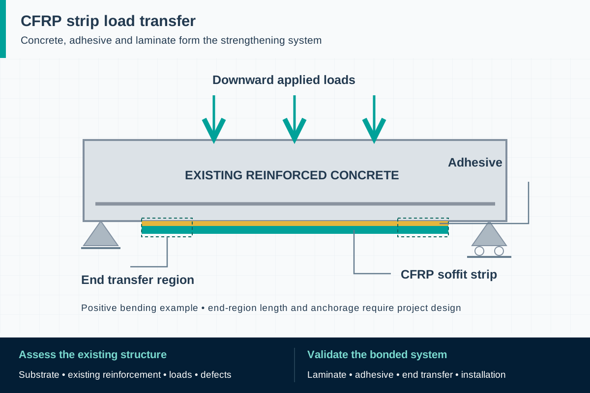
FIG. 1 CFRP concrete strengtheningApplication schematic · not to scale
For this positive-bending case, the CFRP strip sits on the beam's tension face. The adhesive transfers load into the strip, with transfer regions marked at both ends.

Component scope and material selection

F1 can review a component qualification inquiry for pultruded reinforcement against a supplied specification. An accepted strengthening kit, structural design, adhesive selection and site installation require identified specialist responsibilities and project evidence.

Select the complete material system

Project-qualified carbon-fiber laminate, typically with an epoxy matrix; compatible adhesive and substrate repair system selected as an assembly.

Components to specify

  • Flat CFRP strips for externally bonded reinforcement
  • Narrow strips considered for near-surface-mounted reinforcement
  • Project-specific cut lengths and prepared bonding faces

Define what the existing structure must do

A change of building use, increased equipment weight, revised loading or a damaged member can trigger a strengthening study. The first deliverable is an assessment of the existing structure: dimensions, reinforcement, material condition, current loading and the deficiency to be addressed. A strip schedule prepared before that assessment can solve the wrong problem. For example, adding longitudinal reinforcement to a beam does not by itself resolve an inadequate support or a shear-critical region.

Commercial pultruded carbon laminates demonstrate that this is an established civil-engineering application. Each intervention still needs a defined load path and an accountable designer. Separate reinforcement of a sound member from repair of active deterioration; investigate the cause of cracking, corrosion or movement rather than covering the symptom with a bonded strip. The sequence of repairs, temporary support and loading is part of the design brief.

ReferencesEpsilon Composite: pultruded carbon flat laminatesACI PRC-440.2-23: FRP strengthening guide

Choose the position of the reinforcement

Externally bonded strips follow a prepared face of the concrete. Near-surface-mounted strips sit in designed grooves. These arrangements create different construction interfaces: available face width and exposure matter for surface bonding, while cover, existing reinforcement and groove positioning matter for an embedded strip. The choice should be shown on a coordinated drawing with strip direction, termination and intersections, rather than left to the installer.

For an existing floor, map reinforcement and services before proposing cuts. For a beam soffit, establish working access, interruptions at supports and the route for transferring force at each end. Treat curved surfaces, congested junctions, prestressed members and inaccessible terminations as specific design problems. An ordinary flat-strip inquiry does not include prestressing equipment, anchorage hardware or a complete prestressed strengthening system.

ReferencesEAD 160086-01-0301: CFRP strengthening kits

Specify the load-transfer system

Longitudinal stiffness determines how the added reinforcement participates in the member; tensile strength alone is insufficient to select it. The design brief should identify the required material data, test direction, statistical basis and environmental assumptions. Thickness and width define an area, but a larger area is useful only if the concrete and interfaces can develop its force. The reinforcement already present and the strain at the time of bonding also affect the intervention.

Ask the engineer to address strip termination, intermediate cracking, interface failure, anchorage where required, and the consequences of losing the added reinforcement. Coordinate serviceability with ultimate resistance, including movement that may affect finishes or equipment. Existing joints and active cracks require their own treatment. This page provides questions for a specification; it does not provide allowable bond stress, a strip-count formula or a substitute for member calculations.

ReferencesACI PRC-440.2-23: FRP strengthening guide

Turn the design into a controlled installation

Use the selected system's current method statement and project specification. A manufacturer's published example shows why substrate assessment, repair, surface preparation, environmental checks, adhesive control and installation inspection belong in one procedure. Its application temperatures, adhesive thicknesses and curing periods are specific to that system; copying them to an unrelated laminate and resin combination would leave the interface unqualified.

Prepare an installation plan with hold points and named signatories. Record the condition accepted before work, the repair materials, strip identification and the release to proceed. Define how overhead work, access restrictions and nearby operations affect the sequence. Keep the reinforcement protected during handling; carbon-fiber cutting dust is conductive, so plan collection and protection of nearby electrical equipment. State when the strengthened member may return to the intended loading.

ReferencesSika CarboDur System: application method statement

Agree on the acceptance record before bonding

The inspection plan should connect a delivered strip batch to its installed location. Useful records include drawings, material certificates, adhesive identity, installer qualification, environmental observations, inspection results and photographs before access is closed. Agree on who reviews deviations such as a relocated strip, unexpected substrate defect or interruption during installation. Acceptance of the delivered material and acceptance of the finished intervention are separate decisions.

Select inspection methods with the system designer and installer, including their limits and any repair of inspected areas. A sound-looking surface cannot reveal every defect, while a local test cannot characterize every square meter of an installation. The purpose is an agreed evidence package with acceptance criteria and escalation rules. A manufacturer's installation example includes both pre-installation checks and post-installation quality control, demonstrating the need to plan both stages.

ReferencesSika CarboDur System: application method statement

Plan for exposure, damage and future alterations

The operating environment belongs in the original design: moisture, chemicals, temperature, impact, abrasion, ultraviolet exposure and the required fire strategy may lead to different protection details. A high glass-transition value for a laminate does not establish the allowable temperature of the adhesive or the fire resistance of a strengthened member. Identify the controlling element of the assembled system and the evidence needed for the intended service.

Create an accessible as-built record so a later contractor can locate the reinforcement before drilling, chasing services or changing finishes. The maintenance plan should define inspection access, reportable changes and who assesses new cracks, edge lifting, impact marks or damaged protection. Following fire, a significant impact or an increase in loading, arrange a structural review. Cosmetic repair should not conceal damage before its significance has been determined.
ReferencesACI PRC-440.2-23: FRP strengthening guide

Procure a defined scope with a qualification route

Distinguish a laminate manufacturer, a strengthening-system supplier, the structural designer and the installation contractor. Purchasing a pultruded plate addresses only one part of that chain. If a project requires an assessed kit, confirm the actual product combination and documented intended use before substituting any component. A source's successful bridge project is evidence of that source's work, not transferable approval for another supplier.

For component development, agree on a staged decision: review the design inputs, identify the proposed material and surface, test representative samples, and resolve system compatibility before production release. Keep unverified properties marked as pending. F1's existing CFRP-related product content provides a manufacturing discussion starting point; it does not establish a tested concrete-strengthening kit. A useful inquiry states exactly which evidence the project needs and which party will accept it.

ReferencesEAD 160086-01-0301: CFRP strengthening kitsEpsilon Composite: pultruded carbon flat laminates

Standards, regulations and acceptance evidence

The project authority determines the governing jurisdiction and adopted edition. The scope of each reference matters: a material test, an equipment requirement and a workplace rule answer different questions.

Guidance · United States origin; use where accepted by the project designer and authority

ACI PRC-440.2-23

Engineering, construction and inspection guidance for FRP used in externally bonded or near-surface-mounted concrete strengthening.

Application boundary: A guide, not a product certificate or an automatic legal approval. The project design must define enforceable requirements. It is distinct from standards for internal GFRP reinforcing bars.

ReferencesACI PRC-440.2-23: FRP strengthening guide

Standard · Projects adopting this code through the governing code, authority or contract

ACI CODE-440.13-24

Minimum requirements for strengthening existing concrete with the unidirectional externally bonded and near-surface-mounted FRP systems permitted by its Chapter 4.

Application boundary: Publication does not make it law everywhere or certify a product. Masonry is excluded. Seismic strengthening of seismic-force-resisting members in Seismic Design Categories B–F is outside its scope; the designer must establish the applicable route.

ReferencesACI CODE-440.13-24: FRP concrete-strengthening codeACI CODE-440.13-24: official preview and scope

Assessment route · European technical assessment route for construction products

EAD 160086-01-0301

Assessment of concrete-strengthening kits comprising unidirectional carbon/epoxy strips and an epoxy structural bonding agent, for externally bonded or near-surface-mounted use.

Application boundary: Strip width and thickness must be prefabricated in the plant; site cutting to width is excluded. The stated intended use excludes seismic retrofitting and prevention. An EAD is not an ETA: verify the actual kit and assessment scope. EOTA lists the earlier -00 version as superseded.

ReferencesEAD 160086-01-0301: CFRP strengthening kitsEOTA: European Assessment Document register

Public source scopes were reviewed on . These references do not establish certification of an F1 product. Agree the offered grade, finished component, test specimen and acceptance criteria in the project specification.

CFRP concrete strengthening: practical questions

Can I replace any carbon strip with another of the same dimensions?

No. Stiffness, strength basis, surface condition and compatibility with the adhesive and substrate are part of the specified system. A substitution needs review by the designer and, where relevant, the system or assessment holder.

Is a pultruded strip the same product as carbon fabric?

No. A cured strip has a defined section and cannot conform to details in the same way as a fabric installed with resin. Their detailing, installation and qualification need separate consideration.

Does F1 offer an approved concrete-strengthening kit?

This page supports a component qualification inquiry. An approved kit, compatible adhesive, structural design and installation scope must be confirmed with project-specific documentation; none is established merely by the availability of a CFRP laminate.

Can a material test tell me how much load the building can carry?

No. The engineer must assess the existing structure and the strengthened load path, including concrete, connections, bond, other failure modes and serviceability. A laminate tensile result is an input to that work.

How do ACI CODE-440.13-24 and ACI PRC-440.2-23 differ?

The code sets minimum requirements within a defined scope when adopted for the project; the guide provides engineering guidance. Confirm the governing documents with the responsible designer. The code's publication does not make the guide obsolete, and neither document alone qualifies a supplied strip or an installed system.

Technical sources and further reading

Industry sources establish where the application is used. Authority sources define the published scope of standards and regulations. The design and procurement checklists above are an original engineering synthesis for project review.
  1. Standard or public authority

    ISO 10406-3:2019: test methods for CFRP strips

    Test methods for unidirectional pultruded CFRP strips used as externally bonded reinforcement on concrete. Results describe the strip, not a bonded strengthening system.

  2. Industry application evidence

    Epsilon Composite: pultruded carbon flat laminates

    Evidence of a commercial carbon/epoxy strip application in civil engineering; proprietary products and performance are not F1 specifications.

  3. Standard or public authority

    ACI PRC-440.2-23: FRP strengthening guide

    Publisher's scope for engineering, construction and inspection of externally bonded and near-surface-mounted FRP strengthening systems. The full guide is not reproduced.

  4. Standard or public authority

    ACI CODE-440.13-24: FRP concrete-strengthening code

    Official publisher listing for the 2024 design code. Its publication does not establish adoption by a particular jurisdiction or project.

  5. Standard or public authority

    ACI CODE-440.13-24: official preview and scope

    The public preview includes the preface and Sections 1.1–1.2, establishing concrete-only, permitted-system and seismic limits. It does not provide the full design provisions.

  6. Standard or public authority

    EOTA: European Assessment Document register

    Lists EAD 160086-01-0301 and identifies the earlier 160086-00-0301 as superseded.

  7. Standard or public authority

    EAD 160086-01-0301: CFRP strengthening kits

    Sections 1.1–1.2 define the carbon/epoxy strip and bonding-agent kit, manufacturing dimensions and intended-use limits. This assessment document is not an approval of F1 products.

  8. Industry application evidence

    Sika CarboDur System: application method statement

    A manufacturer's system-specific example of installation and inspection controls. Its adhesive, dimensions, environmental limits and cure times must not be transferred to another system.

Prepare a component qualification brief

Provide the application and acceptance requirements so we can assess material, geometry, sampling and the proposed supply scope. We reply within one business day; a formal quotation follows once the specification and delivery are reviewed.

01 · Project country, authority, design basis and responsible structural engineer.
02 · Existing-member drawings, reinforcement survey, condition assessment and current versus required loads.
03 · Externally bonded or near-surface-mounted arrangement; strip orientation, lengths, terminations and interfaces.
04 · Specified laminate stiffness, tensile properties, dimensional tolerances and required test or characteristic-value basis.
05 · Approved adhesive, repair materials, primer or surface treatment, and required evidence for their combination.
06 · Installation access, substrate condition, environmental limits, support requirements and loading restrictions.
07 · Service exposure, protective finish, fire design approach, inspection access and foreseeable alterations.
08 · Sample plan, material traceability, installation inspection, acceptance authority, quantities and delivery schedule.
Get a quoteWhatsApp