Skip to content
Pultrusion application guide

FRP third-rail protection from profile to track assembly

A third-rail cover is part of an operator-defined protection arrangement. Its cross-section, supports, ends and joints must fit the conductor and collector envelope while retaining the required mechanical and electrical performance in service.

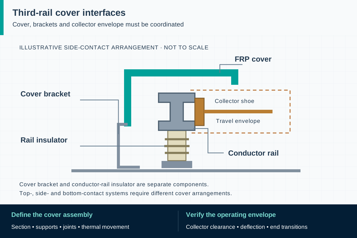
FIG. 1 Third-rail protection systemsApplication schematic · not to scale
Side-contact example: the shoe meets the rail beside its insulating support. The cover bracket is a separate component, and the dashed outline marks collector travel.

Component scope and material selection

F1 can review a drawing-led coverboard component inquiry and the evidence required for qualification. No standard stock cover, approved railway system or safe-access condition is asserted by this guide.

Select the complete material system

Project-qualified glass-reinforced thermoset profiles, with fire and electrical requirements defined for the installation

Components to specify

  • Custom open cover sections
  • Returned-edge coverboards
  • Profile-based joint and end components subject to separate review

Start with the conductor rail and collector envelope

Show whether the system uses top, side or bottom contact, then define the conductor position and the moving collector's permitted envelope. Include tolerances, rail alignment and the access needed for inspection and replacement. The cover must fit that operating geometry in its installed and deflected states. A familiar channel shape does not establish that it will clear the collector or provide the protective arrangement intended by the railway designer.

Coverboards can help restrict unintended approach and address specified environmental exposure, but they do not make an energized track safe to enter or touch. The operating authority determines their function within the wider electrical-safety system. Röchling distinguishes profile-based third-rail covers from compression-molded rail supports; this guide concerns the pultruded cover component. Brackets, insulators, return-current arrangements and access controls need their own design and acceptance basis.

ReferencesRöchling: rail technology and vehiclesBSI: current BS EN 50122-1 release

Design the cover and its supports as one assembly

Map straight runs, joints, curves, conductor ends, transitions and removable maintenance sections. Put the cover's support points and fixing geometry on the same drawing as the protected equipment. Supplied profile length and permissible unsupported span are separate decisions. Identify where the assembly fixes longitudinal position and where it permits the movement required by temperature changes, so neither uncontrolled migration nor restrained expansion is left to the installer to resolve.

The connection review should include bracket stiffness, local bearing, hole or slot geometry, retention against uplift and the risk of edge splitting. Thin returns or snap features need their own load and fit evidence; satisfactory bending of the main cover span does not prove them. Confirm how the cover can be replaced without damaging adjoining parts, and use a representative assembly to verify the interface before committing to a production die.

ReferencesL.B. Foster: coverboards and bracketsRöchling: composite and pultruded profiles

Define location-specific loads and exposure

Prepare a load schedule for the actual installation. Outdoor elevated track can require a different wind and ice assessment from a sheltered tunnel, while debris, handling impacts and maintenance activities introduce localized loads. Have the owner state whether accidental foot loading is a design case. A coverboard should never be advertised as a walking surface merely because a strong laminate is proposed. Check displacement as well as failure, because deflection can create interference before a member breaks.

Record the minimum and maximum component temperatures, solar exposure, wetting, freeze-thaw conditions, salts, cleaning chemicals and expected particulate contamination. Evaluate the retention of the required properties after the agreed conditioning. The surface system, cut ends and drilled locations are part of that exposure assessment. Avoid treating a resin family's general corrosion resistance or a successful indoor electrical test as a prediction of outdoor service life.

ReferencesL.B. Foster: coverboards and bracketsBSI: current BS EN 50122-1 release

Keep electrical protection and fire qualification separate

Ask the railway electrical designer to identify the cover's insulation function, the required tests and relevant interfaces. The laminate's electrical properties do not remove the need to consider contaminated surfaces, accumulated moisture, metal fixings and the surrounding protection arrangement. The designer also establishes what clearances and bonding provisions apply elsewhere in the assembly. A material dielectric-strength number cannot be translated directly into an approved system operating voltage or permission to contact the cover.

Set fire and smoke requirements for the actual location and authority. NFPA 130 addresses transit-system fire and life safety where adopted, while EN 45545-2 addresses materials and components on railway vehicles. A contract may deliberately specify tests from another framework, but that choice should be explicit. Agree on the formulation, thickness, surface treatment and specimen or assembly arrangement covered by each report; a generic flame-retardant label does not define those boundaries.

ReferencesBSI: current BS EN 50122-1 releaseNFPA 130: fixed guideway transit and passenger rail systemsBSI: current BS EN 45545-2 release

Make the installed geometry reproducible

Specify the functional section dimensions, wall thickness, straightness, twist, cut length and hole positions against the approved drawing. The tolerance stack includes the support system and track installation, not only the pultrusion. Use fabrication methods that preserve the qualified edges and surfaces, and agree on inspection criteria for cracks, void indications, exposed fibers and machining damage. A dimensional pass should not override a surface defect affecting an electrical or load-bearing region.

Installation belongs under the operator's isolation, access and work-permit procedures. Trial-fit a representative track section before series installation, checking support spacing, joint movement, end details and collector clearance. The approved installation instructions should define fastening, identification, permitted adjustment and final inspection. If parts do not fit, resolve the drawing or tolerance issue; unapproved field notching, drilling or forced assembly can invalidate both the geometry and the evidence supporting it.

ReferencesRöchling: composite and pultruded profilesBSI: current BS EN 50122-1 release

Use a staged qualification and release process

Begin with a requirements matrix listing the operator, installation environment, standards and their adopted editions, test methods, acceptance criteria and responsible approver. Follow with profile feasibility, representative material and connection evidence, first-article inspection, trial installation and the system checks required by the owner. State which checks apply to raw profile, fabricated cover and installed assembly. None of these stages should be silently replaced by a generic certificate from a different material or thickness.

For serial supply, maintain drawing and formulation revisions, production batch identity and agreed inspection records. Define which changes trigger engineering review or repeated tests, including revised reinforcement, fire additives, coatings, fixing holes and support details. Resolve document approval before releasing parts for track use. This creates a traceable qualification inquiry even where a new profile is technically feasible but railway approval, suitable testing or a verified production route remains outstanding.

ReferencesBSI: current BS EN 50122-1 releaseNFPA 130: fixed guideway transit and passenger rail systems

Inspect retention, surface condition and drainage together

The maintenance plan should look for shifted covers, missing or loose fixings, open joints, distortion, cracking, separation of layers, impact damage and electrical tracking or burn marks. Inspect the conditions that can cause deterioration as well: obstructed drainage, deposits, recurrent collector interference and localized heat. Identify damaged parts by their location and production record so the owner can determine whether a problem is isolated or affects a wider installation batch.

Cleaning, repair or recoating should follow a procedure compatible with the accepted material system and the operator's electrical controls. A coating change can affect the previously reviewed surface or fire behavior. Replacement should restore the approved bracket spacing, clearances and movement detail rather than merely cover a visible gap. Inspection frequency and withdrawal criteria belong to the operator's maintenance program; a component supplier should not promise indefinite life or treat a damaged cover as protective.

ReferencesBSI: current BS EN 50122-1 releaseNFPA 130: fixed guideway transit and passenger rail systems

Standards, regulations and acceptance evidence

The project authority determines the governing jurisdiction and adopted edition. The scope of each reference matters: a material test, an equipment requirement and a workplace rule answer different questions.

Standard · Projects adopting the European fixed-railway electrical-safety framework; national adoption and contract govern.

EN 50122-1:2022+A1:2025

Protective provisions against electric shock in railway fixed installations, coordinated with earthing and the return circuit. The project engineer determines the cover's role in the complete protection arrangement.

Application boundary: An insulating profile alone does not demonstrate compliance of the track installation. Material dielectric data do not establish safe access, clearances or bonding arrangements.

ReferencesBSI: current BS EN 50122-1 release

Standard · North American and other projects where the authority having jurisdiction or contract adopts NFPA 130; the adopted edition can differ.

NFPA 130, 2026 edition

Fire and life safety for fixed guideway transit and passenger rail systems, including stations, trainways and other system elements.

Application boundary: A generic flame-retardant resin declaration does not approve a coverboard installation. The project must identify the material tests, assembly conditions and acceptance criteria applicable to its location.

ReferencesNFPA 130: fixed guideway transit and passenger rail systems

Standard · Railway-vehicle projects adopting EN requirements; a fixed-installation contract may separately specify selected tests.

EN 45545-2:2020+A1:2023

Fire behavior of materials and components on railway vehicles. Its use for a fixed third-rail cover needs an explicit project requirement.

Application boundary: A vehicle material classification is not a universal third-rail approval and does not replace fixed-installation electrical-safety or operator acceptance requirements.

ReferencesBSI: current BS EN 45545-2 release

Public source scopes were reviewed on . These references do not establish certification of an F1 product. Agree the offered grade, finished component, test specimen and acceptance criteria in the project specification.

Third-rail protection systems: practical questions

Can a coverboard replace safe railway access controls?

No. It is one component in an operator-defined protective arrangement. Track access, isolation, clearances and the wider electrical-safety provisions remain governed by the railway's design and operating procedures.

Must every third-rail cover meet EN 45545-2?

EN 45545-2 concerns railway vehicles. A fixed-installation project can specify its tests contractually, but there is no basis for presenting that as the universal third-rail rule. Confirm the owner's fixed-installation electrical and fire requirements.

Are the supporting insulators also pultruded?

Manufacturing routes vary. A system can combine pultruded covers with molded supports, metal brackets and other parts. Each item needs its own drawing and evidence; the pultrusion route of a cover does not describe the whole assembly.

Technical sources and further reading

Industry sources establish where the application is used. Authority sources define the published scope of standards and regulations. The design and procurement checklists above are an original engineering synthesis for project review.
  1. Industry application evidence

    Röchling: rail technology and vehicles

    Identifies profile-based third-rail covers separately from compression-molded conductor-rail supports. Supplier approvals and service history are not F1 evidence.

  2. Industry application evidence

    Röchling: composite and pultruded profiles

    Manufacturing-route reference for pultruded profiles; no competitor material rating is adopted here.

  3. Industry application evidence

    L.B. Foster: coverboards and brackets

    Confirms that coverboard assemblies are adapted to transit-agency criteria and local wind, snow and ice exposure.

  4. Standard or public authority

    BSI: current BS EN 50122-1 release

    Lists BS EN 50122-1:2022+A1:2025 for fixed-installation electrical safety, earthing and the return circuit.

  5. Standard or public authority

    NFPA 130: fixed guideway transit and passenger rail systems

    Official 2026 edition and system scope. The authority having jurisdiction and contract determine the applicable edition and requirements.

  6. Standard or public authority

    BSI: current BS EN 45545-2 release

    Lists 2020+A1:2023 and identifies the railway-vehicle fire scope. It is not automatically the acceptance standard for a fixed third-rail cover.

Prepare a component qualification brief

Provide the application and acceptance requirements so we can assess material, geometry, sampling and the proposed supply scope. We reply within one business day; a formal quotation follows once the specification and delivery are reviewed.

01 · Operating authority, country, project approval route and exact adopted standards and editions.
02 · System operating and maximum voltages, rail cross-section, contact arrangement and collector dynamic envelope.
03 · Cover and bracket CAD, installed tolerances, support spacing, joints, end transitions and removable sections.
04 · Wind, snow, ice, impact and any defined maintenance load, with allowable deflection and connection reactions.
05 · Component temperature range, tunnel or outdoor exposure, contamination, water, cleaning media and drainage arrangement.
06 · Electrical, fire and smoke test matrix, conditioning, accepted thicknesses and surface finishes, and approving parties.
07 · First-article trial location, quantities and cut lengths, installation constraints, identification and batch inspection documents.
Get a quoteWhatsApp