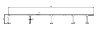
Profile 01
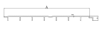
- A
- 609.6
- B
- 28.58
- t1 / t2
- 4.5 / 4.5
Wide shallow panel with repeated underside webs and an edge joint.
Closed-profile fiberglass deck panels separated from open pultruded grating — compare 12 neutral section drawings, nominal A/B/t1/t2 values, joint geometry and project-release requirements.

Structural FRP deck panels use a continuous top surface, repeated underside webs and profile-specific edge geometry. They are evaluated as a deck system with support, joint and connection requirements — not as an I-bar or T-bar grating panel.
The attached source sheet shows 12 variants. F1 has removed the source logo and internal identifiers and publishes only neutral Profile 01–12 references, the section images and the stated A/B/t1/t2 values. No tolerance, unit, material, load, span, fire or waterproofing claim is inferred.
Source note The source sheet labels A, B and t1/t2 but does not state their engineering definitions, unit, tolerance, material, capacity or span. Treat these as nominal drawing values only; the approved F1 drawing controls the project.
Wide shallow panel with repeated underside webs and an edge joint.
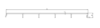
Shallow panel with repeated underside webs and a formed edge return.
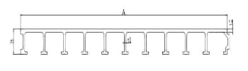
Deep multi-web section with closely spaced internal ribs.
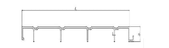
Multi-cell section with interlocking edge geometry.
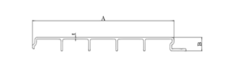
Narrow shallow panel with repeated webs and a stepped edge.
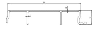
Deep narrow section; shares the source outline with Profile 07 but uses a different thickness set.
Deep narrow section; distinct thickness variant from Profile 06.
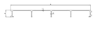
Wide multi-web section; shares the source outline with Profile 09 at a different width.
Width variant of the Profile 08 source geometry.
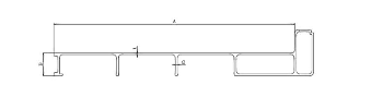
Asymmetric closed-edge section with internal webs.
Interlocking-edge geometry distinct from Profiles 09 and 12 despite matching nominal values.
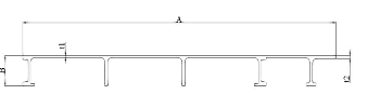
Flat-edge geometry distinct from Profiles 09 and 11 despite matching nominal values.
The source sheet does not state a unit. Confirm the unit for A, B and t1/t2 before using any value in an RFQ, model or approval drawing.
Profiles with matching A/B/t values can still have different edge returns, cavities and interlocks. Choose from the section image, not dimensions alone.
Provide span, support width, uniform and patch loads, load footprint, deflection limit, vibration and any fatigue requirement. The section sheet is not a load table.
Resin, reinforcement, surface, tolerance, fire, slip, connection and capacity must be stated on the project-approved F1 drawing and order datasheet.
A deck panel is a closed-surface or closed-profile section with internal webs and project-specific edge geometry. Pultruded grating is an open-drainage panel assembled from one-way I-bar or T-bar bearing members and cross-rods. Their dimensions, joints, connections and design checks are different, so F1 now documents them on separate product pages.
They are the dimension labels used by the supplied source drawing. The source does not define their engineering meaning or measurement unit. F1 therefore reproduces the nominal values without assigning a unit or interpretation; the approved project drawing must define every dimension.
All three show A 450, B 40 and t1/t2 2.8/4, but their edge and joint geometries are different. They cannot be merged or substituted based on the numeric columns alone.
No stock or tooling claim is made by this page. Profile 01–12 are neutral public references derived from the supplied section sheet after removing its internal IDs. F1 confirms tooling status, minimum order, material system and production availability during quotation.
No. The source sheet provides only the section image and A/B/t1/t2 values. A project needs a separate load/deflection table or engineering calculation tied to the selected material, reinforcement, support condition and load footprint.
They can be evaluated for pedestrian bridges, access decks and replacement-deck systems, but the product section alone does not establish suitability. The bridge engineer must check the governing loads, deflection, vibration, joint load transfer, anti-slip surface, drainage, fire requirements and support connections.
This page does not claim a waterproof assembly. A closed top reduces through-openings, but water tightness depends on panel joints, end closures, penetrations, sealants, slope, drainage and tested assembly details.
Send the candidate profile, the spans and loads, the exposure and the destination. We reply within one business day; a formal quotation follows once the specification and delivery are reviewed.