Continuous cable support
FRP cable trays
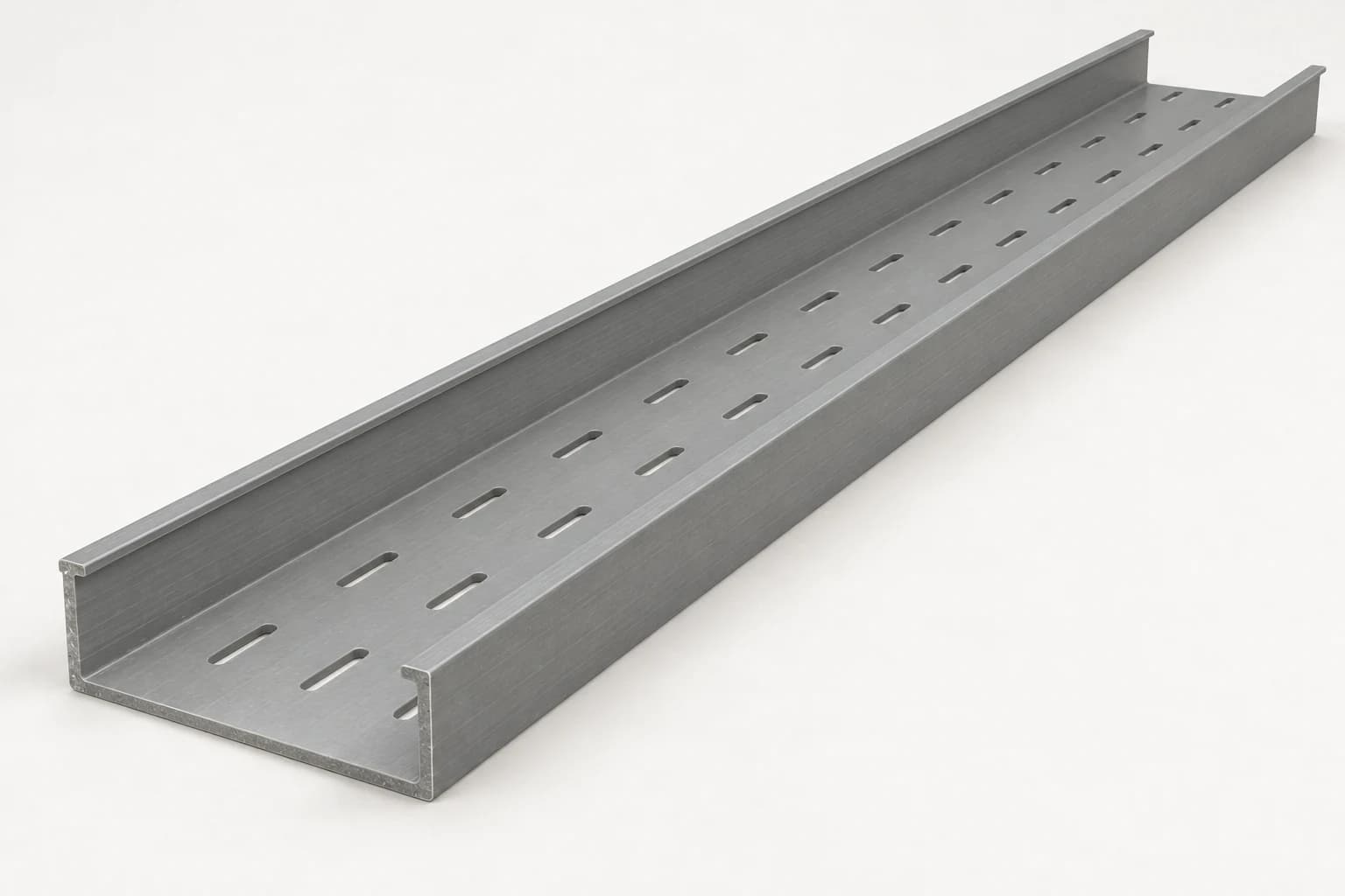
Ventilated or solid-bottom channels for control, instrumentation and cable routes that need a supporting base.
Specify usable width, loading depth, base configuration and covers.
Explore cable trays →Compare FRP cable trays and cable ladders for corrosive environments. Define tray bases, ladder rungs, resins, supports, fittings and project requirements.
Start with your name and email. Route drawings and details can follow.
Ventilated or solid-bottom channels for control, instrumentation and cable routes that need a supporting base.
Specify usable width, loading depth, base configuration and covers.
Explore cable trays →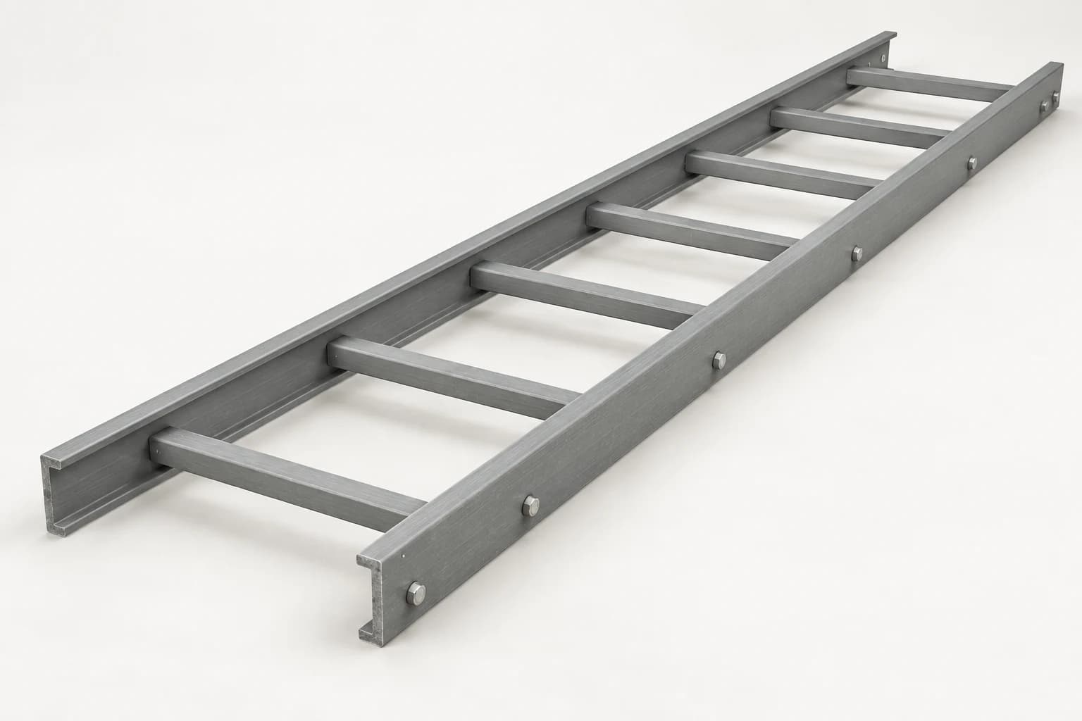
Open ladder sections for power cable routes where ventilation, drainage and access to cable restraints matter.
Specify rail depth, usable width, rung spacing and the load / span requirement.
Explore cable ladders →AI-generated product illustrations informed by supplier references. Profiles, slot patterns and connections are illustrative; confirm the offered configuration in the quotation.
FRP cable trays and ladders carry power, control and instrumentation cables through wet, coastal and chemically aggressive environments. Their support channels, brackets and frames complete the load path into the structure.
F1 Composite supplies pultruded fiberglass profiles and agreed fabricated components for these routes. Start with the cable arrangement and environment, then define the tray, supports, fittings and evidence needed for your project.
A tray provides a supporting base; a ladder carries cables on spaced rungs. “Ladder-type cable tray” is another name for a cable ladder. Here, cable tray refers to channel and trough configurations so the two constructions are easy to compare.
| Configuration | Useful starting point | Check before selection |
|---|---|---|
| Open cable ladder | Power cables and larger cable runs where ventilation, drainage and access matter. | Rung spacing, cable support requirements, cleat attachment, rail depth and bend radius. |
| Ventilated / perforated tray | Control and instrumentation routes that need more frequent cable support. | Cable diameter, opening pattern, drainage, fill allowance and declared load capacity. |
| Solid-bottom / covered tray | Routes requiring a continuous base or protection from falling debris and sunlight. | Heat dissipation, cover retention, drainage, inspection access and outdoor uplift. |
| Trunking / wireway | Enclosed routing where access control and cable containment are specified. | The applicable enclosure / trunking requirements; do not infer an IP rating from appearance. |
A fiberglass channel or trough combines side walls with a supporting base. A ventilated version has openings for airflow and drainage; a solid-bottom version provides a continuous surface. Choose the opening pattern against cable size and support requirements. Small cables still need a suitable contact surface at joints and route changes.
Define opening size, pattern and usable base width. Check cable bearing, drainage and the load rating of the perforated section.
Specify a continuous base where the cable arrangement requires it. Review heat dissipation and drainage for the route conditions.
Schedule cover sections and retaining hardware separately. Covers add protection from debris or sunlight; they do not establish an IP rating.
Specify: usable width, loading depth, wall / base thickness, straight-section length, base configuration, bend radius, resin and any cover requirements. Dimensions and available tooling are confirmed for the offered product.
A fiberglass cable ladder uses two longitudinal rails connected by transverse rungs. Its open construction leaves access for cable fixing and allows air and water to pass between rungs. Suitability for a power-cable route depends on the actual rail section, rung design, joints and tested load arrangement.
Specify usable width and rail depth, then check the complete section against cable mass, span and deflection limits.
Agree rung pitch, cable contact surface and the manufacturer’s connection detail. Fastening and bonding must follow the offered system.
Coordinate cable cleats, separation, bend radius and fitting supports. Short-circuit restraint requires its own cable and cleat assessment.
Rung spacing and support span are different dimensions. Rung spacing is the distance between cable-bearing cross members. Support span is the distance between brackets or frames carrying the complete ladder. Neither can be inferred from the supplied section length.
Humid galleries, treatment basins and dosing areas
Provide washdown chemicals, splash conditions, temperature and local gas exposure. Keep brackets accessible for inspection and avoid liquid traps.
Process areas, utilities and corrosive service corridors
Identify each chemical and concentration, continuous versus occasional exposure, and cleaning conditions. Specify compatible resin and connection hardware.
Salt spray, exposed pipe racks and marine utilities
Consider UV, wind on covers, vibration, temperature and the full fastener system. Offshore approval requirements must match the actual product and project.
Substations, service tunnels and instrument routes
Coordinate cable separation, cleat forces and electrical clearances. Tunnel and transit routes need project-specific fire, smoke and toxicity criteria.
The environment can change along one cable route. Treat a chemical dosing bay, a sheltered gallery and an exposed roof as separate selection conditions where necessary.
Channel or angle crossarms connect to a wall rail or base plate. Check bracket projection, eccentric loading, bolt bearing and anchor forces in the actual substrate.
A cross-channel carries the tray between suspension points. Specify rod and hardware materials, overhead attachment, lateral restraint and any seismic requirements.
Square-tube posts, channels and bracing support independent routes. Check frame stability, base fixings, impact exposure and access around equipment.
| Group | Items to schedule | Coordination question |
|---|---|---|
| Route changes | Horizontal bends, tees, crosses, reducers and vertical risers | Does every fitting respect the cable’s minimum bending radius and have the required local support? |
| Connections | Splice plates, bolts, washers, expansion connections and hold-downs | Do joints and fixed / sliding points follow the offered system’s tested arrangement? |
| Cable organisation | Dividers, cable ties, cleats and identification | Are segregation, cable restraint and short-circuit duties specified separately? |
| Protection & interfaces | Covers, cover clamps, end treatments, support brackets and anchors | Are wind exposure, cut edges, substrate and dissimilar-material interfaces addressed? |
Chemical resistance belongs to a particular resin and laminate under defined exposure conditions. Ask for a compatibility review covering concentration, temperature, contact duration and mechanical loading.
A candidate for many humid and outdoor industrial routes. Confirm compatibility with the actual chemicals, cleaning regime and temperature.
A candidate for more demanding chemical service. Specify the resin grade and check the complete exposure profile before approval.
Define flame, smoke and toxicity tests separately. Outdoor routes also need an agreed UV protection strategy and cut-edge treatment.
| Material | Why it may fit | Tradeoff to review |
|---|---|---|
| Glass FRP | Corrosion resistance in compatible chemical service; insulating structural material; manageable component weight. | Stiffness, sustained-load behaviour, temperature, fire criteria and connection detailing. |
| Galvanized steel | High stiffness and familiar support details for many industrial routes. | Coating suitability, damaged or cut surfaces, corrosion exposure and maintenance access. |
| Stainless steel | Mechanical robustness and corrosion resistance where a suitable grade is selected. | Specific chemical and chloride exposure, weight, installed cost and bonding requirements. |
| Aluminum | Low weight and useful corrosion resistance in suitable environments. | Chemical compatibility, galvanic interfaces, thermal movement and electrical bonding. |
Compare supply, fittings, installation access, shutdowns and maintenance over the project’s intended service period. A universal price saving or service-life claim is not a sound basis for choosing the material.
Eaton · fiberglass cable ladder & channel tray ↗Select the complete load path: cables → tray rungs and rails → crossarm or bracket → frame and connections → anchors and supporting structure. Each part needs appropriate evidence.
List installed cable mass per metre, future allowance, tray and cover self-weight, and any concentrated or installation loads. Define wind, ice, seismic and other site actions where applicable.
Read load capacity together with support spacing, deflection, splice position and end-span conditions. A multi-span result cannot automatically be used for a single span or a cantilever.
Review creep, temperature effects and environmental reduction factors using the offered laminate and system data. Ask which factors are already included in the published allowable load.
Check bracket bending, bolt bearing, connection slip, pull-out and substrate anchorage. Cleat forces and cable short-circuit restraint need their own assessment.
For example, Øglænd’s FOE page states that its IEC load-test arrangement uses an end span reduced to three-quarters of the support spacing, with no splices in that end span. This is a condition attached to that manufacturer’s data, not an F1 installation rule.
The calculator checks an individual profile. It does not qualify the cable tray system, cantilever connection, anchors, cable cleats or fire performance. Enter the actual support geometry, loads and material data.
Agree the destination-market requirements, applicable edition and acceptance documents before procurement. The standards below describe different scopes; their appearance here is not a claim that every F1 component holds a system approval.
| Reference | What it addresses | What to request |
|---|---|---|
| IEC 61537 | Cable tray and cable ladder systems for supporting cables; its scope excludes trunking and ducting. | System identification, applicable edition, test configuration and load / deflection evidence. |
| UL 568 | Nonmetallic cable tray evaluation for the relevant market. | If required, a verifiable listing or certification record covering the exact offered system. |
| EN 13706 / ASTM D3917 | Pultruded-profile requirements / dimensional tolerances, respectively. | Profile and laminate documentation; these do not replace cable-system testing. |
| ASTM E84 / specified fire tests | Surface burning or other explicitly specified fire behaviour. | The actual specimen, method and result. A surface-burning test does not establish circuit integrity or structural fire endurance. |
| IEC 61914 | Cable cleats and intermediate restraints, including declared electromechanical duties. | Evidence for the cable arrangement, cleat spacing and relevant short-circuit forces. |
| Legacy NEMA FG 1 references | Historical fiberglass cable-tray classifications still seen in catalogues. | Clarify the contractual requirement: FG 1 was rescinded in November 2017. Do not present it as a current standard. |
Non-conductive FRP does not provide electromagnetic shielding and is not a grounding conductor. The electrical designer must resolve bonding of metallic parts, cable segregation, static and lightning risks for the installation.
Freeze the route drawing, fitting schedule, support positions and connection details. Check cable pulling access, replacement access and clearances around equipment.
Follow the supplied system’s instructions for cutting, drilling, dust control, edge sealing, tightening and splice placement. Do not apply steelwork torque values or improvise field holes.
Record the installed configuration and approved load allowance. Inspect for loose fasteners, damaged fibers, missing clamps, cover movement and unauthorized additions; set inspection intervals for the site.
Cable trays and cable ladders support cables. Do not use them as walkways, climbing ladders or personnel supports.
Mita · installation guidance ↗| Input | Information to send | Why it matters |
|---|---|---|
| Supply boundary | Raw profiles, fabricated supports, tray sections or complete system; engineering and installation responsibilities. | Makes the offered package and exclusions explicit. |
| Geometry | Tray base / opening pattern or ladder rung spacing; route drawing, width, loading depth, length, bends, risers, reducers and minimum cable bend radius. | Defines straight sections, fittings and usable space. |
| Cable and support loads | Cable schedule, mass per metre, future allowance, point loads, spans and support arrangement. | Sets system capacity and individual support checks. |
| Exposure | Chemicals and concentrations, splash or immersion, temperature range, UV and coastal exposure. | Guides resin, surface protection and hardware selection. |
| Interfaces | Wall / floor / overhead structure, bracket projection, anchors, hole patterns and access restrictions. | Defines connection loads and fabrication details. |
| Acceptance evidence | Project standards and editions, fire / smoke requirements, electrical criteria and inspection documents. | Aligns the proposed configuration with the approval process. |
| Delivery | Quantities, destination, required date, transport length limits, kit marking and packing needs. | Supports a practical production and logistics scope. |
You can start with your name and email. This checklist helps refine the technical scope; it is not a requirement to complete every field before contacting us.
A channel or trough tray has a supporting base, which may be solid or ventilated. A cable ladder has two side rails joined by spaced rungs and an open bottom. Manufacturers also use ‘ladder-type cable tray’ for the latter. Specify the construction, not just the name; select it against cable support needs, ventilation, restraints and the system’s load data.
In this application, these terms usually describe glass-fiber-reinforced polymer cable supports. The name alone does not define the resin, reinforcement, construction, load rating or fire performance. Compare the offered system and its documentation.
Tell us whether you need profile lengths, cut and drilled support components, fabricated supports or a complete tray package. F1 supplies pultruded profiles and agreed components; complete trays, bends, covers, hardware and system test evidence must be confirmed in the quotation against your specification.
There is no universal FRP support span. Use the supplied system’s load table with the actual cable load, temperature, deflection criteria, splice layout and end-span arrangement. Check wall brackets, crossarms, connections and anchors separately. A length supplied from the factory is not an allowable span.
Glass FRP is electrically insulating, but this does not remove the project’s earthing, bonding or lightning-protection requirements. Metallic components and connected equipment need assessment by the electrical designer. FRP is not an equipment grounding conductor or an electromagnetic shield.
No. Compare the exact resin and laminate with the chemicals, concentration, exposure mode, operating temperature and mechanical loads. Vinyl ester is often considered for more demanding chemical service; it is not a guarantee of compatibility with every chemical or process.
A flame-spread or flammability result does not establish structural endurance, circuit integrity, smoke or toxicity performance. State the required test, classification, duration and tested assembly. Tunnel, rail and offshore requirements need their own evidence.
Only after reviewing cable fill, heat dissipation, added mass, support capacity and access. Covers also introduce fixing and wind-uplift demands outdoors. Keep the original design allowance and accepted changes in the route records.
Start with your name, email and project scope. A route sketch, cable schedule, tray dimensions, support spacing, environment, required standards, quantities and destination help refine the quote. Drawings and technical details can follow after the first enquiry.
This guide draws on public system documentation from Eaton, Enduro / Creative Composites Group, Øglænd, Mita / Wibe Group and Niedax Ebo, plus the tray and ladder product examples from Sai Seeya Composite. Standards publishers provide the separate test-scope references. Their product ratings and approvals apply to their own systems. References checked September 21, 2026.
Send the dimensions, quantity, service environment, and destination. We acknowledge requirements within one business day.