Skip to content

F1-GRID · pultruded grating

Pultruded FRP Grating — T-Bar & I-Bar

Select pultruded fiberglass grating for one-way spans, industrial platforms and walkways. Compare 36 T-bar, I-bar and specialty configurations with matched M/J/T clips.

Whole panels or drawing-based requirements. Quantities, fabrication and delivery scope confirmed with your quote.

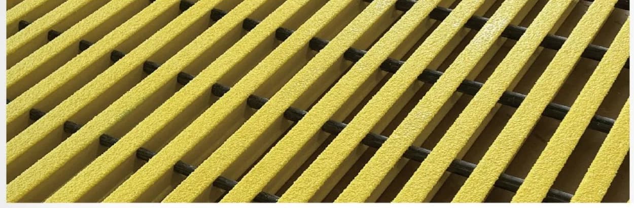
Yellow pultruded fiberglass bearing bars and transverse cross-rods
Product construction reference. Confirm resin, surface and final geometry for the selected configuration.
Depth range
25–76 mm
Listed configurations
36 bearing-bar rows
Load direction
Along bearing bars
Fixing hardware
M/J/T · 316SS

Select • compare • prepare your inquiry

Build your grating requirement

Start with what you know. Keep unknown details for review; attach drawings on the contact form.

Choose your starting point

Directional Stiffness · Longer Spans

Pultruded bearing bars for open, span-driven grating layouts

For F1's glass-reinforced products, pultruded fiberglass grating means an open, one-way glass-fiber-reinforced polymer (GFRP) panel assembled from pultruded I-bar or T-bar bearing members and cross-rods. Project specifications often call the same product pultruded FRP grating; the quoted series, resin system, surface and load/deflection table still control.

Every selection starts with the clear span and bearing-bar direction. Match the series to load, deflection, resin, fire, slip and opening requirements; then issue the panel cut plan and M/J/T hold-down arrangement on the approved project drawing.

Close-up of yellow pultruded FRP grating bearing bars with a rough walking surface and transverse cross-rods
Pultruded grating construction detail. The photograph shows bar and cross-rod construction but does not establish a specific series, resin or slip rating.
Pultruded Product Configurations

T-bar, I-bar, high-load and high-open systems

Pedestrian T-Bar Grating

Wide-top T-shaped bearing bars create a comfortable walking surface while retaining open drainage. Dedicated series reduce the dominant opening for pedestrian and accessibility-governed routes.

Bearing-bar form
Pultruded T-bar
Catalog depths
25 and 38 mm
Typical uses
Walkways, platforms, mezzanines, public-access routes

Industrial I-Bar Grating

Pultruded I-shaped bearing bars concentrate continuous glass reinforcement in the span direction. Select the series from support spacing, deflection limit, open area and project load case.

Bearing-bar form
Pultruded I-bar
Catalog depths
25, 30 and 38 mm listed below
Typical uses
Industrial access, chemical plants, offshore walkways, cooling towers

High-Load & Cooling-Tower Series

High-load rows use deeper or more closely spaced bearing bars; cooling-tower rows prioritize open area and airflow. Neither label replaces the project-specific load/deflection table.

High-load reference
HI-4720
High-open reference
SI-8315 · 83% nominal open area
Release requirement
Approved span, support, load and deflection schedule
Pultruded Series Data

Common I-bar and T-bar production configurations

Compare all 36 bearing-bar configurations below. Dimensions are millimeters; weight is nominal kg/m². Approximate inch depths are for reference. Choose a row to prefill your quotation request. Confirm resin, dimensions, tolerances and project load/deflection data before release.

Pedestrian T-bar series

Wide-top T bearing bars for pedestrian access and reduced clear openings.

Pultruded grating nominal selection specifications
TypeDepth (mm)Bearing-bar center (mm)Cross-bar center (mm)Open areaWeight (kg/m²)Quotation
T-1210250.984 in43.4152.4012%14.5Quote this spec: T-1210
T-1810250.984 in50.8152.4018%13.8Quote this spec: T-1810
T-2510250.984 in50.8152.4025%13.6Quote this spec: T-2510
T-3310250.984 in61.0152.4033%11.2Quote this spec: T-3310
T-3810250.984 in61.0152.4038%10.2Quote this spec: T-3810
T-1215381.496 in43.3152.4012%19.6Quote this spec: T-1215
T-2515381.496 in50.8152.4025%16.7Quote this spec: T-2515
T-3815381.496 in61.0152.4038%14.2Quote this spec: T-3815

Industrial I-bar & T-bar series

I-bar configurations and deeper T-bar options for one-way industrial platform spans.

Pultruded grating nominal selection specifications
TypeDepth (mm)Bearing-bar center (mm)Cross-bar center (mm)Open areaWeight (kg/m²)Quotation
I-4010250.984 in25.4152.4040%17.1Quote this spec: I-4010
I-5010250.984 in30.0152.4050%14.2Quote this spec: I-5010
I-6010250.984 in38.1152.4060%11.2Quote this spec: I-6010
I-40125301.181 in25.4152.4040%19.8Quote this spec: I-40125
I-50125301.181 in30.5152.4050%17.4Quote this spec: I-50125
I-60125301.181 in37.1152.4060%13.5Quote this spec: I-60125
I-4015381.496 in25.4152.4040%22.0Quote this spec: I-4015
I-5015381.496 in30.5152.4050%19.1Quote this spec: I-5015
I-6015381.496 in37.1152.4060%16.1Quote this spec: I-6015
T-3320501.969 in38.1152.4033%20.3Quote this spec: T-3320
T-5020501.969 in50.8152.4050%15.7Quote this spec: T-5020

High-load HI / HL series

Deeper, denser bearing-bar systems; final load and allowable span come from the project table.

Pultruded grating nominal selection specifications
TypeDepth (mm)Bearing-bar center (mm)Cross-bar center (mm)Open areaWeight (kg/m²)Quotation
HI-4710250.984 in30.2152.4047%27.6Quote this spec: HI-4710
HI-4715381.496 in30.2152.4047%40.0Quote this spec: HI-4715
HI-4720501.969 in30.2152.4047%54.5Quote this spec: HI-4720
HI-4725642.520 in30.2152.4047%61.6Quote this spec: HI-4725
HI-4730762.992 in30.2152.4047%73.6Quote this spec: HI-4730
HI-5810250.984 in38.1152.4058%21.0Quote this spec: HI-5810
HI-5815381.496 in38.1152.4058%31.8Quote this spec: HI-5815
HI-5820501.969 in38.1152.4058%42.5Quote this spec: HI-5820
HI-5825642.520 in38.1152.4058%48.9Quote this spec: HI-5825
HI-5830762.992 in38.1152.4058%58.6Quote this spec: HI-5830
HL-4020501.969 in25.4152.4040%70.4Quote this spec: HL-4020
HL-5020501.969 in30.0152.4050%52.2Quote this spec: HL-5020
HL-6020501.969 in38.1152.4060%43.5Quote this spec: HL-6020

High-open SI series

Large-open-area I-bar rows for airflow-sensitive applications such as cooling-tower walkways.

Pultruded grating nominal selection specifications
TypeDepth (mm)Bearing-bar center (mm)Cross-bar center (mm)Open areaWeight (kg/m²)Quotation
SI-7310250.984 in30.2152.4073%13.2Quote this spec: SI-7310
SI-7315381.496 in30.2152.4073%18.6Quote this spec: SI-7315
SI-8310250.984 in47.6152.4083%8.5Quote this spec: SI-8310
SI-8315381.496 in47.6152.4083%12.0Quote this spec: SI-8315

Cross-bar center is listed as 152.40 mm throughout the overview table. Accessibility, maximum panel size, stock status, resin, surface and load capacity require separate order confirmation.

Selection & Approval Checks

Four checks before releasing a pultruded grating layout

1

Confirm bearing-bar direction

Pultruded grating is a one-way spanning product. Mark the span direction on the panel-layout drawing and support every cut bearing-bar end.

2

Check service and deflection

Select resin, bar depth and spacing against the chemical environment, temperature, support spacing, concentrated load and governing deflection limit.

3

Choose the walking surface

Match open area and slot direction to drainage, airflow, accessibility and dropped-object requirements; then confirm a profiled surface or a fine-grit or coarse-grit treatment for the selected series.

4

Issue the clip layout

Choose M, J or series-specific T hold-downs from the bearing-bar profile and support access. The approved drawing controls quantity, spacing and complete fastener assembly.

See what to specify

Use these drawings to describe the support layout and the supply you need. Schematics only, not measured product or installation drawings.

Bearing bars bridge the supports →Clear span: between support facesSupportSupport

Specify the span, not just the panel length

For pultruded panels, mark bearing-bar direction on the layout. Cross-rods do not provide equivalent spanning capacity. Include support width, loads, cutouts and deflection requirements.

P01P02Whole panelsCut & markedFixing kitsConfirm dimensions, cutting, packing and freight scope

Choose the supply scope

Request whole panels or finished pieces against a drawing. Add panel marks, openings and fixing requirements. Packing, kit contents and delivery arrangements are confirmed with the quotation.

Before choosing a thickness

Specify the opening, surface and service conditions

Pitch: center to centerClear openingSchematic only · not to scale
A mesh designation or bar-center dimension is not the unobstructed opening. Confirm the top clear opening and direction of travel where footwear, dropped objects or accessibility govern.

Match the resin to the environment

Identify chemical names, concentrations, exposure type and operating temperature. Discuss polyester or vinyl ester against that service; resin names alone do not establish compatibility.

Read about FRP resin systems →

Choose the walking surface

For molded mesh, compare concave and gritted finishes. For pultruded bars, confirm the profile finish or bonded grit for the selected series. Match the surface to wet or dry use, footwear and cleaning, and specify the required slip-test method and acceptance criteria.

Check the full load case

State clear span, support width, uniform and concentrated loads, contact area and deflection limit. Cutouts, edge support and bearing-bar direction belong on the panel layout.

Request the applicable load data →
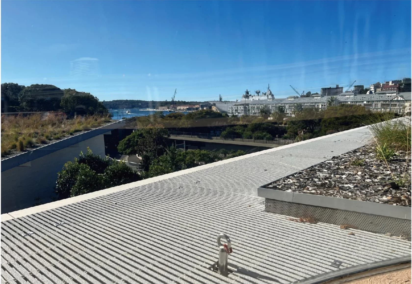
Open pultruded FRP grating installed as a rooftop walking surface
Pultruded Grating · 316SS Hardware

M, J, and T clips for pultruded FRP grating

F1 pultruded-grating clip kits are selected against the I-bar or T-bar series, panel depth, support detail and underside access. The approved drawing fixes the exact hold-down geometry and complete fastener assembly. The diagrams explain compatibility and load path only — they are not fabrication dimensions.

M, J, and T are F1-GRID pultruded-grating product definitions. Letter names are not standardized across manufacturers; the F1 SKU, compatible bearing-bar series and approved project drawing control.

F1-GRID clip M

M hold-down clip

F1-GRID-CLIP-M-316
M hold-down clipSchematic section of an M hold-down spanning two adjacent grating bars and fastening the panel to a support. Typical installation, not to scale.supporting memberhold-down actiongrating bargrating bar
Typical installation — not to scale

Seats across two adjacent grating bars to hold an open-mesh panel to its supporting member.

Material
316 stainless steel (316SS)
Connection
Panel to support
Compatible
Molded grating · Pultruded grating
Installation
Use only where the clip seats fully on the selected mesh or bearing-bar profile and the approved support attachment can be installed and inspected.

Boundary: Panel depth, bar profile, support geometry, and access determine the final hardware arrangement.

F1-GRID clip J

J support-hook clamp

F1-GRID-CLIP-J-316
J support-hook clampSchematic section of an upper grating clip and lower J hook clamping a panel around a support flange without drilling the support. Typical installation, not to scale.support flange — not drilledlower J hookapproved upper clipgrating bargrating bar
Typical installation — not to scale

Pairs a lower J hook with an approved upper clip and fastener to clamp the panel to a support flange without drilling the support frame.

Material
316 stainless steel (316SS)
Connection
Panel to support
Compatible
Molded grating · Pultruded grating
Installation
Match the approved variant to the molded mesh or pultruded open area and to the support-flange geometry, with the lower hook fully engaged below the flange.

Boundary: The J hook and upper clip are not universal; the approved drawing must match the grating opening, support flange, fastener, and installation access.

F1-GRID clip T

T pultruded-grating clip

F1-GRID-CLIP-T-316
F1 T pultruded-grating clipSchematic section of an F1 T clip between pultruded-grating bearing bars and fastened to a support frame. Typical installation, not to scale.support frameF1 series-specific hold-downbearing barbearing bar
Typical installation — not to scale

F1 series-specific hold-down definition for fastening selected F1 pultruded-grating bearing-bar series to a support frame.

Material
316 stainless steel (316SS)
Connection
Panel to support
Compatible
Pultruded grating
Installation
Use only with the F1 pultruded series and support arrangement identified on the approved project drawing.

Boundary: The T designation is not standardized across manufacturers and must not be treated as a generic cross-brand geometry or fit claim.

Installation and spacing principles

  1. 1Select the clip from the grating family, panel depth, bearing-bar or mesh geometry, support detail, and installation access — not from the letter alone.
  2. 2Locate M, J, or T panel-to-support hold-downs only at supporting members. Secure each pultruded panel independently; clips do not increase the approved span.
  3. 3Review the support and hold-down layout again after field cuts, penetrations, or unsupported panel edges are introduced.
  4. 4The approved project drawing governs final clip geometry, bolt and washer selection, quantity, spacing, edge clearances, and tightening requirements.

Typical starting layout

General coordination values before project-specific fastening design.

Each support line
Minimum 2 panel-to-support hold-downs
Each panel
Minimum 4 panel-to-support hold-downs
Along a support
1200 mm / 4 ft maximum between hold-downs
Bearing at support
38 mm / 1.5 in minimum bearing length

These are general starting coordination values, not a final fastening design. The approved project drawing, project engineer, grating series, support condition, and applicable manufacturer requirements control the final layout.

Combined CAD detail

F1 Pultruded Grating Clips — M/J/T (316SS)

One family-specific DXF containing the M/J/T typical installation details and F1 SKU references. Project-specific geometry remains governed by the approved project drawing.

Download M/J/T DXF

Free DXF · no login · verify revision before issue for construction

Final clip geometry, bolt and washer selection, quantity, spacing, edge clearances, and tightening requirements must be shown on the approved project drawing. The clip guide does not change the grating span, bearing, support, or connection design checks.

Walking Surface Options

Profiled, fine-grit and coarse-grit pultruded surfaces

Profiled Surface

Confirm the bearing-bar surface profile and whether added grit is required for the selected series. Specify the slip-test method and service conditions; a profiled finish is different from a molded concave surface.

Fine Grit

A bonded fine-grit surface for outdoor platforms, wet areas and routine industrial access. Confirm the project slip-test method and acceptance value in the order specification.

Coarse Grit

A more aggressive surface for offshore, process-water, oily or chemical-splash duty. Cleaning method and footwear exposure should be reviewed with slip performance.

Engineering & downloads

Match the documents to your panel

Download the current selection data and clip drawings. For a load/deflection table or test report, identify the panel and service conditions so the documents match the proposed supply.

Inside the selection CSV

DepthWeightOpen area
25 mm14.5 kg/m²12%
25 mm13.8 kg/m²18%
25 mm13.6 kg/m²25%

Nominal selection data · not a load table

Panel selection data

Spreadsheet-ready CSV with the same dimensions, nominal weights and open areas shown on our product pages. Selection reference, not a load table.

Download pultruded specifications (CSV) ↓

Project load & test data

Include series or mesh, clear span, support width, uniform/point load, load footprint and deflection limit. State resin, chemical exposure, temperature and any fire or slip-test requirement.

Request matching engineering data →

Project & bulk procurement

Plan the supply as well as the panel

For US, Canadian, Australian, New Zealand and UK enquiries, include the destination and required units. Panel specification, quantity, cutting, fixing kits, packing and freight determine the quoted scope.

01

Quantity & samples

Send panel quantities or total area, your preferred configuration and sample needs. Minimum production quantity and sample arrangements are confirmed with the quotation.

02

Whole panels or a cut plan

State the required finished sizes, openings, edge treatment, panel identification and fixing kits. We confirm the drawing and fabrication scope before order release.

03

Packing & destination

Give the delivery country, port or postcode and site handling constraints. The quotation defines packing, freight scope and the agreed Incoterm.

04

Production & transit

Share your required-on-site date. Production timing and transport time are confirmed separately after specification, quantity and destination review.

Have a drawing, or still choosing?

We will acknowledge your requirements within one business day and confirm the next step. A formal quotation follows specification and delivery review. Attach your layout to the enquiry, or describe the application and ask us to help shortlist a configuration.

Quote a drawing or schedule →

Catalog dimensions identify standard section options, not live inventory. Confirm tooling, material, quantity and production timing in the quotation.

Frequently Asked Questions

What is pultruded FRP grating?

Pultruded FRP grating is assembled from continuous-fiber I-bars or T-bars connected by cross-rods. Most reinforcement runs along the bearing bars, producing high stiffness and strength in the designed span direction. It must be oriented and supported as a one-way spanning panel.

Are pultruded fiberglass grating and pultruded FRP grating the same product?

For F1's glass-reinforced products, yes. Both terms refer here to open, one-way GFRP panels assembled from pultruded I-bar or T-bar bearing members and cross-rods. FRP is a broader material term, so the project specification should still define the glass reinforcement, resin system, series, surface and load/deflection requirements. Molded FRP grating and closed structural FRP deck panels are separate product families.

How is pultruded grating different from molded grating?

Pultruded grating is selected for longer one-way spans and higher directional stiffness. Molded grating is cured as a bidirectional mesh panel and is generally more forgiving when a layout needs many irregular cutouts. Molded mesh sizes, nominal panel weights and M/C/J clips are now documented on the separate molded FRP grating page.

How is pultruded grating different from a structural FRP deck panel?

Pultruded grating is an open-drainage assembly of one-way I-bar or T-bar bearing members and cross-rods. A structural deck panel has a continuous top surface, internal webs and profile-specific edge geometry. Deck sections, joints and A/B/t values are documented on the separate FRP deck-panels page.

Which pultruded grating series are suitable for pedestrian routes?

Start with the dedicated T-bar pedestrian rows or the I-4010 row shown in the specification table, then verify the actual clear opening and direction of travel against the accessibility code adopted by the project. A series label or a pedestrian badge does not replace the project authority's opening and surface review.

Can pultruded FRP grating be cut on site?

Yes, using carbide- or diamond-tipped tools with dust extraction and suitable PPE. Keep the bearing bars in the designed span direction, provide support under cut bearing-bar ends, seal cut surfaces with compatible resin and re-check the hold-down arrangement.

Which clips are used with pultruded grating?

F1 uses compatible M saddle hold-downs, J support-hook assemblies and series-specific T hold-downs. Clip letters are not universal across manufacturers, so order by F1 SKU, bearing-bar series and approved drawing rather than by the letter alone.

Are the M, J and T clips supplied in 316 stainless steel?

Yes. The F1 pultruded-grating clip kits listed on this page are specified in 316 stainless steel. Final geometry, bolt length, complete fastener assembly, quantity, spacing and tightening requirements are issued for the selected panel and support detail.

Where can I get a pultruded grating load table?

Send the series, clear span, support width, uniform and concentrated loads, load footprint and deflection limit. F1 will return the applicable project load/deflection table and panel-layout assumptions. Do not substitute a generic load-class label for the selected bearing-bar row.
Have a question about this product?

Our FRP Engineering Advisor answers spec, sizing, and chemical-compatibility questions instantly — and routes complex ones to the right human.

Pre-filled question: “I need pultruded FRP grating for [application]. Candidate I-bar/T-bar series [or unsure], clear span [mm], support width [mm], uniform and point loads [details], deflection limit [L/...], opening/accessibility requirement [details], resin/chemical exposure [details], support flange and underside access [details]. Please select the panel series, M/J/T 316SS clips and required load-table/approval documents.

Ask the AI advisor →

Need pultruded I-bar or T-bar grating with matched 316SS clip kits?

Send the dimensions, quantity, service environment, and destination. We acknowledge requirements within one business day.