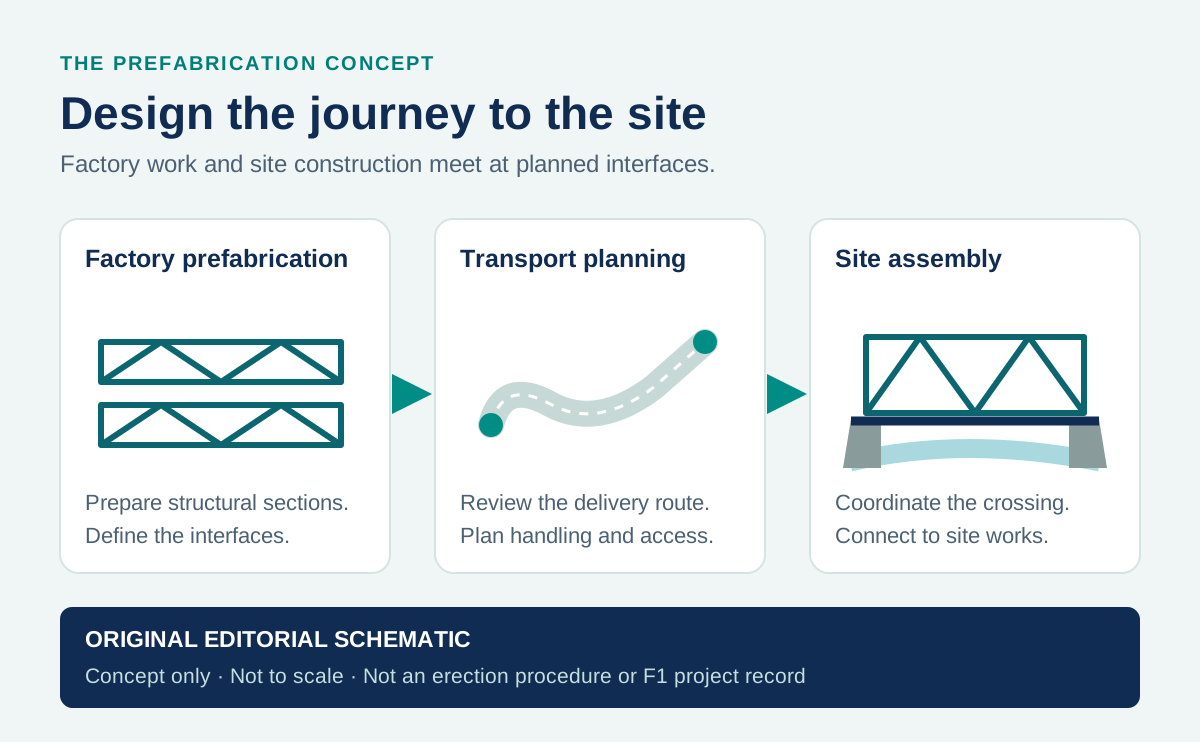
Clear width and user mix
Measure between barriers and size for forecast peak demand, operating envelope, passing and any pedestrian–cycle separation.
A source-backed guide to active-user beam bridges: load paths, clear width, barriers, joints, vibration, FRP detailing and three public case studies.
Direct answer
A beam bridge carries its deck on horizontal beams or girders between supports. On a pedestrian or cycle crossing, the load path normally runs from the deck through cross-members or deck action into the longitudinal girders, then through bearings or end connections to the substructure, foundations and ground.
The structural definition follows public explanations from Victoria's Big Build and the FHWA beam-bending reference. The animated diagram is conceptual, not a project design.
Published
Aug 31, 2026
Updated
Sep 1, 2026
Technical Review
Haifeng Gong, Ph.D.
Standards and application check
Standards and References
Structural behaviour
Downward loading bends the main girders: the upper region is generally in compression and the lower region in tension, with high shear demand toward the supports. A continuous bridge also develops negative bending over intermediate supports. The deck, connections, bearings and substructure are not secondary annotations—they are the links that make the path complete.
Lateral load follows a different route through the deck diaphragm, cross-frames, bearings or restraints and substructure. Wind on a high barrier or screen can alter both force and aerodynamic response, so the edge system must be included in the structural model.
Pedestrians, cycles, barriers, wind and self-weight first act on the deck system.
Deck action and cross-members distribute load into the longitudinal beams or girders.
Support details transfer reactions while accommodating the movement defined by the design.
Abutments, piers and foundations complete the load path into competent ground.
Positive bending dominates between two supports; movement is usually managed at the ends.
Continuity can reduce midspan demand but adds negative bending and restraint effects over piers.
I-, T- and box-girders are member forms. The FHWA notes that beam and girder are often used interchangeably.
Terminology reference: FHWA bridge types and girder forms.
Pedestrian and bicycle geometry
An active-user beam bridge is not a road bridge with traffic loads removed. The usable corridor is defined by clear width, approach alignment, gradients, sightlines, barrier geometry, joints, drainage, lighting and the behaviour of people on foot, bicycles, wheelchairs and mobility devices.
Queensland TMR lists 3.0 m minimum clear width between barriers for two-way cycling and shared pedestrian–cycle use. The Transport for NSW toolbox gives a 4.0 m desired minimum for a shared path. Both are jurisdiction-specific; demand, separation and owner approval govern the project.
Sources: Queensland TMR 2024 criteria and Transport for NSW toolbox.
Measure between barriers and size for forecast peak demand, operating envelope, passing and any pedestrian–cycle separation.
Cyclist edge protection, accessible handrails, openings, pannier clearance and post setbacks are separate geometric decisions.
Keep the wheel path free of abrupt lips, unsafe gaps and loose cover plates; coordinate movement with a smooth surface detail.
Coordinate slip resistance, crossfall, scuppers, kerbs and discharge so water does not pond or create hazards below.
Explicitly include or exclude service and emergency vehicles in the design brief and drawings; do not leave the load model implicit.
Bearings, cross-members, drainage and concealed connections need a safe inspection and replacement strategy from day one.
Australian project route
Australian bridge work starts with the adopted AS/NZS 5100 series, then applies the road authority's active-transport requirements and the current Austroads Guide to Road Design Part 6A. Adoption, editions and project amendments must be confirmed in the brief; a web article cannot establish compliance. See Standards Australia and Austroads Part 6A.
Dynamic serviceability
Walking, running and crowd movement can excite vertical, lateral and torsional modes. In the AS/NZS 5100-based TMR guidance, a pedestrian bridge with vertical resonant frequency below 5 Hz requires a vibration serviceability investigation; special consideration is also required when the fundamental horizontal frequency is below 1.5 Hz.
Passing those screens does not prove comfort. The analysis still needs mode shape, modal mass, damping, pedestrian density and peak acceleration. The European Commission JRC/HIVOSS guide frames the same problem around comfort, lock-in risk, intentional excitation, testing and response mitigation.
A 2023 Monash pultruded-GFRP research footbridge measured first vertical frequencies around 5.9–6.2 Hz, yet walking tests produced a reported peak acceleration of 2.86 m/s². It was a specific 9 m prototype without its final accessories—not a universal FRP result—but it shows why frequency alone is insufficient.
Balanced assessment
Evidence-led examples
These are publicly documented references selected for different lessons: a major concrete cycle bridge, a lightweight FRP cycleway system and a university-tested hybrid GFRP footbridge. None is represented as an F1 Composite project.
Indooroopilly, Brisbane, Australia · Prestressed-concrete T-girder cycle bridge
Why this case matters
A cycle-only crossing that demonstrates how a conventional repeated-girder system can be designed around rider continuity, off-site fabrication and maintenance access—not just structural capacity.
Why this case matters
A cycle-only crossing that demonstrates how a conventional repeated-girder system can be designed around rider continuity, off-site fabrication and maintenance access—not just structural capacity.
Bicentennial Bikeway, Brisbane, Australia · Glued pultruded-FRP girder system
Why this case matters
Queensland TMR documents a cycleway bridge using glued pultruded-FRP hollow sections with an engineered cementitious composite plate deck—a useful short-span reference where access and lifting mass matter.
Why this case matters
Queensland TMR documents a cycleway bridge using glued pultruded-FRP hollow sections with an engineered cementitious composite plate deck—a useful short-span reference where access and lifting mass matter.
Ovar, Portugal · Hybrid GFRP–SFRSCC simply supported beam bridge
Why this case matters
Developed through Portuguese university–industry research, this full-scale bridge links laboratory static, dynamic and creep testing with an in-service pedestrian beam system monitored after installation.
Why this case matters
Developed through Portuguese university–industry research, this full-scale bridge links laboratory static, dynamic and creep testing with an in-service pedestrian beam system monitored after installation.
Research basis
No single publication covers the whole decision. The design picture becomes more reliable when owner guidance, standards bodies, full-scale research and long-term field evidence are read together.
Owner guidance for active-user geometry, barriers, loads, vibration screening, maintenance access and value-for-money system selection.
A human-induced vibration methodology covering comfort, lock-in risk, measurement, modal identification and response control.
Full-scale static, dynamic and creep testing plus later in-service modal assessment of the São Silvestre hybrid footbridge.
The 2025 second-edition LRFD guide updates the US design route for FRP pedestrian bridges and delegated system design.
ATS 5880-25 treats FRP bridge members as controlled, documented and tested manufactured products, not dimension-only catalogue items.
Twenty-five-year Pontresina evidence shows why retained stiffness must not be presented as unchanged strength or maintenance-free service.
FRP beam bridge design
Pultruded FRP can reduce lifting mass and remove conventional steel corrosion from the composite member, which is useful at corrosive or difficult-access sites. It is not a one-for-one steel substitution. Pultruded members are orthotropic, and lower stiffness means deflection, shear deformation, vibration, local bearing and connection deformation can govern before material strength is fully used.
The current design and procurement route depends on jurisdiction. In the United States, AASHTO published the second edition of its LRFD guide for FRP pedestrian bridges in 2025. In Australia and New Zealand, Austroads ATS 5880-25 Ed. 1.1 sets manufacturing requirements for members assembled from standard pultrusions or bespoke vacuum-infused mouldings. The bridge owner's code and specifications still govern the final system.
Use direction-specific tension, compression, bending and shear data. Thin webs and flanges also need local buckling and support checks.
Lower modulus and low mass can make serviceability govern. Include bending, shear deformation, creep, modal mass, damping and acceleration.
Qualify bolt bearing, net section, adhesive durability, slip, deck-to-girder transfer, barrier anchors and concentrated bearing reactions.
Define resin, UV protection, temperature and moisture reductions, wear surface, drainage and a damage-tolerant inspection plan.
Fire response depends on resin, geometry, protection, exposed faces and load. Treat vandalism, impact and replacement access explicitly.
Specify traceability, production verification, lift points, temporary bracing, transport envelope, tolerances and bearing installation.
A 2026 long-term Pontresina study reported unchanged global bridge stiffness after 25 years, while alpine-exposed material samples retained about 70% of initial tensile strength. Pontresina is a truss, not a beam-bridge case; the evidence is used here only to show that stiffness retention is not proof of unchanged strength.
Resin chemistry, member geometry, exposed surface, protective layers, design load and fire scenario determine performance. Neither “fireproof” nor a blanket failure statement is defensible without a tested assembly and project fire strategy.
Screen the whole bridge system before asking for a profile quotation.
The F1 FRP beam calculator and span tables organise preliminary member checks. They do not model pedestrian vibration, bearings, bridge-system load distribution, fatigue, accidental actions or owner acceptance.
A beam bridge carries its deck on one or more horizontal beams or girders spanning between abutments, piers or both. Deck loads reach the main members through deck action or cross-members, then pass through bearings or end connections into the substructure and foundations.
The terms are often used interchangeably. In practice, girder usually describes a larger primary beam, while I-girder, T-girder and box-girder identify member geometry. The structural family is still governed by beam action: bending and shear between supports.
There is no universal width. Clear width is measured between barriers and must follow the owner, jurisdiction, forecast peak flow, user mix and separation strategy. Queensland lists 3.0 m minimum clear width for two-way cycling and shared use, while the Transport for NSW toolbox gives a 4.0 m desired minimum for a shared path—showing why the jurisdiction must be stated.
People can excite vertical, lateral and torsional modes through walking, running and crowd movement. Natural frequency is only a screening variable; modal mass, damping, mode shape, pedestrian density and peak acceleration determine comfort. In the Australian framework, vertical frequencies below 5 Hz trigger investigation and lateral frequencies below 1.5 Hz require special consideration.
No bridge should be specified as maintenance-free. FRP avoids conventional steel-corrosion mechanisms in the composite member, but surfacing, joints, drainage, bearings, bolts, adhesive interfaces, UV protection, fire damage and concealed deck-to-girder connections still need planned inspection and repair access.
Only when the design brief and governing load model include it. The owner should deliberately include or exclude maintenance and emergency vehicles, state the decision on the drawings and control physical access accordingly.
There is no single material limit. Span is a system decision involving girder depth, continuity, deck action, vibration, transport, erection and owner criteria. Queensland TMR describes multi-beam FRP systems as a practical short-span option around 12 m, while longer active-user beam bridges commonly use steel or prestressed concrete; neither figure is a universal maximum.
Project measurements are transcribed from transport-agency records or peer-reviewed research. The six diagram subjects use original desktop and mobile compositions, not copied project drawings or photographic proof. Every project is labelled as a public reference and not an F1 Composite delivery.
Give the advisor your span, clear width, user mix, load model, exposure and governing owner. It will organise missing inputs and relevant F1 profile data; it does not replace the bridge engineer.
Pre-filled question: “I am evaluating an FRP pedestrian or cycle beam bridge. Help me structure the preliminary inputs for geometry, loads, vibration, connections, durability, erection and the RFQ without treating the result as final bridge design.”
Send the dimensions, quantity, service environment, and destination. Engineering responds within one business day.