Skip to content
Specialist component specification

Carbon-fiber tube components for an engineered roller

A tube inquiry should identify the structural shell and the work needed to turn it into a roller. Separate material and geometry requirements from precision finishing, assembly, balancing and machine acceptance.

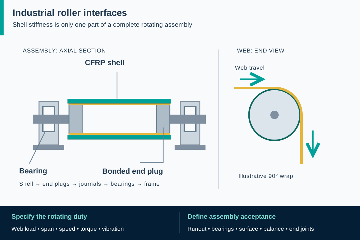
FIG. 1 Carbon-fiber roller tube componentsComponent schematic · not to scale
The axial section connects shell, plugs, journals, bearings and frame. The separate end view shows tangent web entry and exit around a quarter-turn wrap.

Component scope and material selection

F1 can assess a component feasibility inquiry against a drawing and load schedule. Tube process, dimensions, machining, end fittings and finished-roller services are subject to technical review and explicit scope confirmation.

Select the complete material system

CFRP construction selected for the proposed shell duty; longitudinal, transverse and angled reinforcement requirements must be defined.

Components to specify

  • Candidate tubular roller shells
  • Shell blanks with controlled machining allowances
  • Pultruded reinforcement elements for a separately designed assembly

Define the shell and its datums

Provide outside diameter, inside diameter or wall definition, length and the surfaces used as datums. Explain whether tolerances apply to a manufactured blank or a finished component. Specify straightness, roundness and concentricity only with the measurement length, support and condition needed to interpret them. A long shell supported differently during inspection can produce a different observation, so agreement on the method is as useful as a tolerance number.

Show the working face, end insertion zones, shoulders and any areas that will later be machined. Define allowances without assuming that unlimited material can be removed from the laminate. Add the mating-end drawings or identify the party developing them. If outer diameter is fixed by the machine, include the available space for wall thickness, coatings and end features so the material proposal can address the real envelope.

ReferencesISO 1101:2017: geometrical specification languageISO 5459:2024: datums and datum systemsEpsilon Composite: technical carbon rollers

Specify the duty before selecting a construction

The shell brief needs bearing span, radial loads, torsion where driven, operating speed and the intended connection arrangement. Provide stiffness targets and local-contact conditions along with any mass objective. Ask the supplier to identify the proposed reinforcement architecture and its limitations. A requirement for carbon fiber does not by itself specify bending stiffness, shear response or resistance to local pressure.

Some established roller constructions use pullwinding or combine pultruded elements with wound layers. That application evidence is a reason to evaluate process suitability, not a promise that one process can cover every tube. Confirm whether the proposed component can be made within the available manufacturing scope, then agree on representative test evidence. If the required construction needs a specialist partner or another process, resolve that before tooling or production commitments.

ReferencesEpsilon Composite: pultrusion and filament-winding hybrid

List every operation beyond the tube blank

Create a scope table for cutting, machining, end-fitting supply, bonding, coating, grinding, assembly and balancing. Mark the responsible party and acceptance point for each operation. The first delivery may intentionally be an unfinished shell; the drawing and packaging should make that status clear. A material supplier's inspection report should not be interpreted as acceptance of work performed later by an assembler.

For surface coatings, define the contact material, cleaning exposure, profile and roughness required by the process. For end fittings, agree on fit, retention, installation loads, galvanic isolation from metal journals and the inspection of the completed joint. For static control, request the applicable surface and assembly test rather than an assumption based on fiber conductivity. These interface decisions can influence the shell design, so communicate them before approving its nominal dimensions.
ReferencesEpsilon Composite: technical carbon rollersISO 21940-11:2016: balancing rigid-behavior rotorsISO 21940-12:2016: balancing flexible-behavior rotors

Keep component acceptance separate from rotor acceptance

Agree on incoming checks for geometry, visual condition, identification and specified material evidence. State how transport damage is documented and who can authorize rework. For a prototype, include a review of manufacturing deviations before the component is built into an assembly. Inspection of an inaccessible surface or joint may need to happen earlier in the sequence; the quality plan should identify that hold point.

The finished-rotor specification belongs to the party responsible for the assembled roller. It should address the actual attachments, service speed, balancing basis and machine checks. A balance requirement cannot be verified on a bare shell as though journals, coatings and bearings were already present. Preserve records through subsequent operations, and define which changes require renewed acceptance. The final release should identify both the delivered configuration and the limits of the approved use.

ReferencesISO 21940-11:2016: balancing rigid-behavior rotorsISO 21940-12:2016: balancing flexible-behavior rotors

Standards, regulations and acceptance evidence

The project authority determines the governing jurisdiction and adopted edition. The scope of each reference matters: a material test, an equipment requirement and a workplace rule answer different questions.

Standard · International; when specified for the rotor

ISO 21940-11:2016/Amd 1:2022

Balancing procedures and residual-unbalance tolerances for rotors with rigid behavior.

Application boundary: The purchaser must define the applicable rotor configuration, service speed and acceptance criteria. This is not a universal balance grade for every carbon tube or long roller.

ReferencesISO 21940-11:2016: balancing rigid-behavior rotorsISO 21940-11:2016/Amd 1:2022

Standard · International; flexible-behavior rotor applications

ISO 21940-12:2016

Balancing methods and guidance for rotors with flexible behavior.

Application boundary: The official scope does not make it a universal rotor acceptance specification and excludes structural resonances. A satisfactory balance result does not establish the entire machine's vibration performance.

ReferencesISO 21940-12:2016: balancing flexible-behavior rotors

Public source scopes were reviewed on . These references do not establish certification of an F1 product. Agree the offered grade, finished component, test specimen and acceptance criteria in the project specification.

Carbon-fiber roller tube components: practical questions

Does the tube quotation include balancing?

Only if specifically included and technically defined. Balancing and final rotor acceptance normally depend on the complete configuration, including end fittings and surface treatments.

Can I machine a standard tube to the final roller diameter?

Only within an approved machining plan and allowance. Removing material can interrupt reinforcement and change structural performance, so the laminate and final geometry must be reviewed together.

Is a pultruded carbon tube suitable for every driven roller?

No. Torque, local pressure and end connections may require reinforcement directions or a manufacturing process beyond a predominantly longitudinal pultrusion.

Technical sources and further reading

Industry sources establish where the application is used. Authority sources define the published scope of standards and regulations. The design and procurement checklists above are an original engineering synthesis for project review.
  1. Industry application evidence

    Epsilon Composite: technical carbon rollers

    Application evidence for converting, printing and nonwoven machinery. Describes pullwinding and hybrid manufacture; its finished-roller claims do not establish F1 capabilities.

  2. Industry application evidence

    Epsilon Composite: pultrusion and filament-winding hybrid

    Explains that some high-performance tubes combine pultruded reinforcement and wound layers. K1 is a proprietary process, not an F1 process claim.

  3. Standard or public authority

    ISO 1101:2017: geometrical specification language

    Official scope for indicating and interpreting form, orientation, location and run-out requirements. It does not set a roller tolerance or inspection support arrangement; the purchase checklist is original project guidance.

  4. Standard or public authority

    ISO 5459:2024: datums and datum systems

    Defines the indication and interpretation of datums in technical documentation. Its public scope excludes the verification operator; measurement fixtures and conditions need separate agreement.

  5. Standard or public authority

    ISO 21940-11:2016: balancing rigid-behavior rotors

    Official scope for balancing procedures and tolerances when the rotor has rigid behavior.

  6. Standard or public authority

    ISO 21940-11:2016/Amd 1:2022

    Published amendment to Part 11; establish the contractual edition and amendments with the purchaser.

  7. Standard or public authority

    ISO 21940-12:2016: balancing flexible-behavior rotors

    Official scope and limitations for flexible rotors, including the exclusion of structural resonance assessment.

  8. Standard or public authority

    ISO 12100:2010: machinery risk assessment

    General machinery design, risk assessment and risk reduction; not a material certification.

  9. Standard or public authority

    OSHA 29 CFR 1910.212: machine guarding

    US workplace requirements concerning machine hazards such as rotating parts and ingoing nip points.

Prepare a component qualification brief

Provide the application and acceptance requirements so we can assess material, geometry, sampling and the proposed supply scope. We reply within one business day; a formal quotation follows once the specification and delivery are reviewed.

01 · Shell drawing with datums, OD/ID, length, wall definition and tolerances for the actual delivery stage.
02 · Bearing span, load schedule, torque, speeds, temperature, mass and stiffness targets.
03 · Proposed reinforcement architecture, required material evidence and process restrictions.
04 · End-fitting drawings, insertion zones, machining allowances and assembly responsibilities.
05 · Working surface, coating, cleaning exposure, static requirements and finish acceptance.
06 · Prototype inspection, production traceability, packaging, balancing owner and final assembly acceptance.
Get a quoteWhatsApp