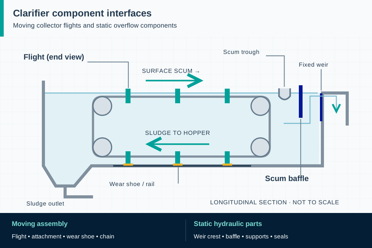
Send an approved section drawing with the overall depth, width, wall arrangement and relevant radii. Identify the surfaces used for attachment, wear shoes and scraping or guiding. If the original component has a built-in lip, show its orientation in the assembled mechanism. A photograph can explain the application, but it cannot define drilling datums or the relationship between the flight and its accessories.
The collector designer should identify which dimensions control fit and which control structural performance. Specify the cut-length datum, attachment-hole pattern, end clearances and any local filling or reinforcement. Add an assembly drawing showing the chain connections, wear-shoe positions and travel direction. Mark left/right or leading/trailing distinctions where needed so a dimensionally correct part cannot be fitted in the wrong orientation.
ASTM D3917 can supply a baseline for standard pultruded-profile tolerances. A special flight may need different limits at equipment interfaces, established explicitly on its drawing. Do not assume a general straightness tolerance also defines acceptable running clearance. Discuss tolerances with the profile manufacturer and equipment designer before committing to tooling.