Skip to content
Specialist component specification

Carbon-fiber profiles for robotic beams and struts

Specify a beam blank or strut body by its functional load path and interfaces. The purchase description must distinguish a pultruded profile from a machined part and a validated assembly with end fittings.

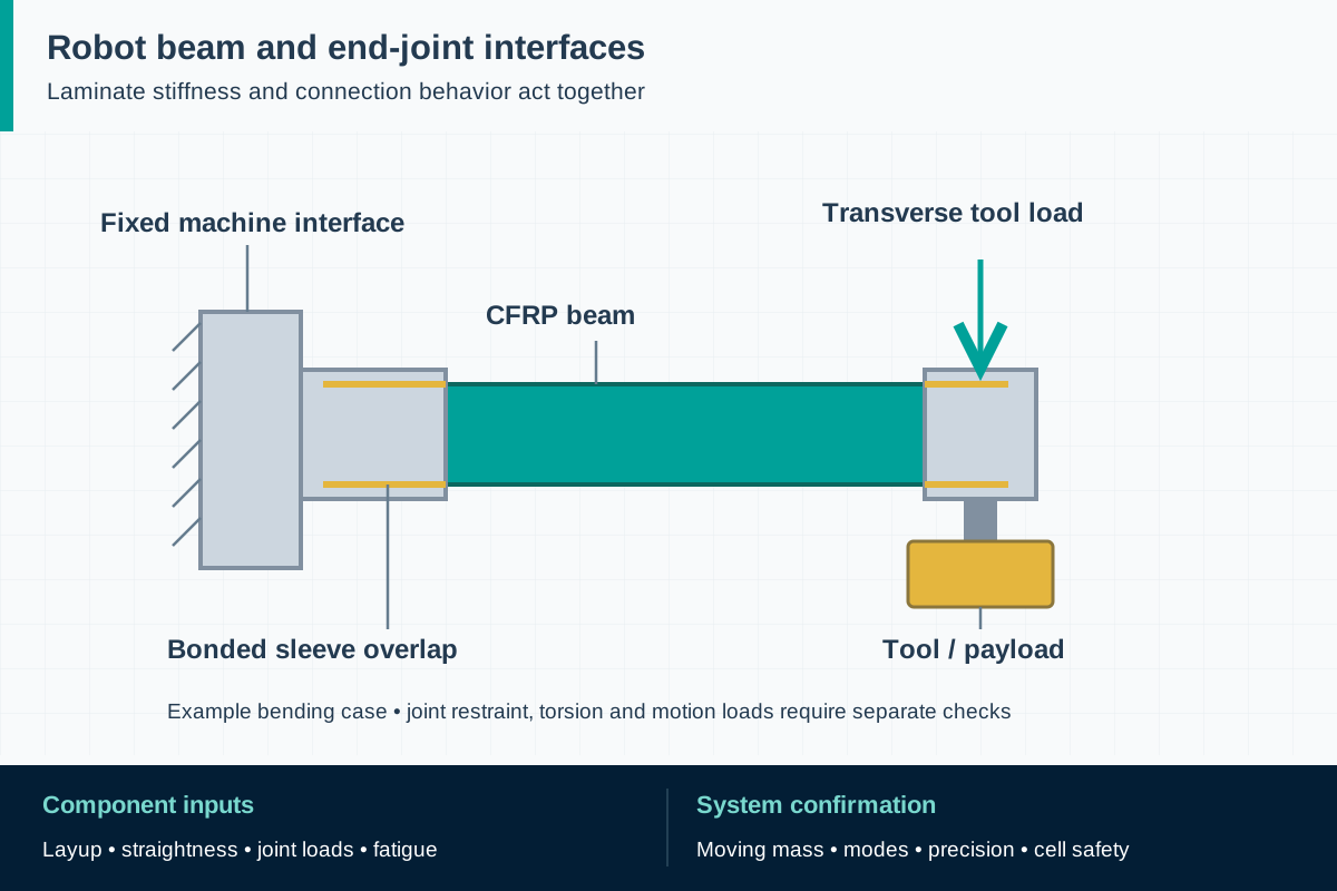
FIG. 1 Carbon-fiber robotic beam componentsComponent schematic · not to scale
One cantilever bending case: follow the load from the tool adapter through the beam and bonded sleeve to the fixed machine root. Torsion and dynamic cases require separate checks.

Component scope and material selection

F1 can review proposed pultruded carbon component requirements. No stock robot-arm series, dimensional capability, completed joint qualification or robot safety approval is implied; manufacturing and inspection scope require confirmation.

Select the complete material system

Proposed CFRP architecture and resin selected against the OEM's mechanical and environmental requirements; properties to be substantiated for the delivered profile.

Components to specify

  • Constant-section round strut bodies
  • Rectangular or square beam blanks
  • Custom straight profiles with drawing-controlled interface zones

Define the delivered condition

Choose the procurement boundary explicitly: cut profile, machined blank, profile with separately supplied fittings, or bonded and inspected member. State which party owns structural design, adhesive selection, fitting design and assembly validation. A quotation for a tube should not be read as including a complete robot link.

Attach a revision-controlled interface drawing with functional datums and identify any dimensions that apply only after assembly. For repeat orders, retain the accepted construction rather than ordering only by outer diameter and wall thickness. A change in reinforcement can leave those dimensions unchanged while altering the member's behavior.

ReferencesEpsilon Composite: carbon-fiber delta robot armsEpsilon Composite: carbon beams for industrial machines

Match reinforcement to all load directions

The specification should state the required axial and flexural behavior, relevant transverse and shear properties, and the design basis for compression. Thin walls, local clamping and torque may govern even where a longitudinal tensile result looks adequate. Ask for properties of the proposed cured profile with test direction and conditioning identified.

Define whether additional off-axis or circumferential reinforcement is needed and how it will be manufactured. Do not label every carbon tube as conventional pultrusion. Select the section and architecture with the OEM, and record which performance inputs remain subject to prototype verification.

ReferencesEpsilon Composite: standard-profile catalogNASA TP-3512: buckling of composite beams

Specify connection zones and metrology

Describe bore or outer-surface fit, usable bond area, end squareness, straightness and rotational orientation from meaningful datums. A general length tolerance cannot control the center distance of an assembled link. Agree on how temperature, support points and measurement force will be controlled during inspection of a slender member.

Show forbidden drilling and clamping zones, any load-spreading inserts, and the required surface condition for bonding. Metal-contact isolation, surface preparation and dimensional machining can interact, so approve them as a coordinated detail. Inspect relevant features before an end fitting makes them inaccessible.

ReferencesNASA: bolted joints for pultruded carbon-epoxy reinforcementEpsilon Composite: standard-profile catalog

Release prototypes against an evidence plan

Ask the customer to identify the material, joint and assembled-member tests needed before production release. Link each test to a failure mode or performance requirement. Typical decisions include how to represent load reversal, moisture and temperature, and whether a credible handling defect must be included in the assessment.

Keep a clear boundary between development specimens and production parts. Record the tested material and process revision, dimensions, joint construction and conditioning. If an accepted prototype needs a production-process change, determine the required requalification before shipment; appearance and nominal dimensions are not sufficient evidence of equivalence.

ReferencesFAA AC 20-107B with Change 1: composite structural substantiationISO 12100:2010: machinery risk assessment

Control delivery and later replacement

Agree on the production inspection record, lot identification, packaging supports and protection of prepared surfaces. State whether witness samples, retained material or customer hold points are required. Avoid identification methods that cut fibers or contaminate a critical bonding face; approve the marking position on the drawing.

The receiving OEM should verify the component revision before installing it, then complete its machine checks. Replacement instructions must preserve fitting orientation and the accepted assembly procedure. Robot-performance and safety validation remain with the responsible machine parties; a carbon-profile inspection report does not close those obligations.

ReferencesISO 9283:1998: robot performance and testingISO 10218-2:2025: robot applications and cells

Standards, regulations and acceptance evidence

The project authority determines the governing jurisdiction and adopted edition. The scope of each reference matters: a material test, an equipment requirement and a workplace rule answer different questions.

Standard · International machinery design; apply through the project conformity route

ISO 12100:2010

Risk assessment and risk reduction for the machine, including foreseeable misuse and life-cycle activities.

Application boundary: A low-mass beam is one design input. It does not establish the safety of motion controls, guarding or human access, and this standard supplies no generic CFRP allowable stress.

ReferencesISO 12100:2010: machinery risk assessment

Standard · Industrial robot and robot-cell programs adopting these standards

ISO 10218-1:2025 and ISO 10218-2:2025

Part 1 addresses industrial robots; Part 2 addresses integration, industrial robot applications and cells.

Application boundary: Not standalone profile certificates. The robot builder and integrator determine applicability and validation. Medical robots and lifting or transporting people are outside Part 1's scope; this page concerns industrial handling machinery.

ReferencesISO 10218-1:2025: industrial robotsISO 10218-2:2025: robot applications and cells

Standard · Industrial robot performance specifications where contractually adopted

ISO 9283:1998

Methods for specifying and testing robot performance characteristics, distinct from safety requirements.

Application boundary: The purchaser must select the relevant characteristics and acceptance conditions. A beam dimensional report does not establish the assembled robot's accuracy, repeatability or settling behavior.

ReferencesISO 9283:1998: robot performance and testing

Regulation · European Union; applicable machinery placed on the market or put into service

Regulation (EU) 2023/1230 (Machinery Regulation)

Determine the applicable route under Directive 2006/42/EC or Regulation (EU) 2023/1230 against the relevant date; the regulation generally applies from 20 January 2027.

Application boundary: Specified provisions apply earlier. A profile is not automatically machinery or a separately regulated safety component. The responsible manufacturer must determine the supplied item's role and the effect of a retrofit on conformity.

ReferencesEUR-Lex: machinery safety requirements and transition dates

Public source scopes were reviewed on . These references do not establish certification of an F1 product. Agree the offered grade, finished component, test specimen and acceptance criteria in the project specification.

Carbon-fiber robotic beam components: practical questions

Is this a catalog of certified replacement arms?

No. It is a component specification route for an OEM qualification project. No interchangeability with a particular robot model is asserted.

Can holes be added after delivery?

Only where the accepted design and machining procedure allow them. A new hole can interrupt load-carrying fibers and change local failure modes, so it needs design review.

What is the minimum information needed for a useful inquiry?

Provide the interface drawing, loads and motion, dimensional envelope, operating environment and requested delivery condition. These establish whether a profile blank is suitable and what development evidence is still needed.

Technical sources and further reading

Industry sources establish where the application is used. Authority sources define the published scope of standards and regulations. The design and procurement checklists above are an original engineering synthesis for project review.
  1. Industry application evidence

    Epsilon Composite: carbon beams for industrial machines

    Application evidence for machine gantries and handling structures. Describes pultrusion as well as hybrid processes; its dimensions, tolerances and performance are not F1 specifications.

  2. Industry application evidence

    Epsilon Composite: carbon-fiber delta robot arms

    Documents tubes with assembled end fittings for delta robots. Published acceleration, cycle-rate and accuracy claims belong to that supplier and are not reproduced as design values.

  3. Industry application evidence

    Epsilon Composite: standard-profile catalog

    Distinguishes reinforcement/process variants and identifies a glass protective layer on a carbon profile. Not a catalog of F1 tooling or stock.

  4. Standard or public authority

    NASA TP-3512: buckling of composite beams

    Research on laminate architecture, shear-center position and twisting of open-section composite beams. Engineering background, not a robot design code or pultruded-product qualification.

  5. Standard or public authority

    NASA: bolted joints for pultruded carbon-epoxy reinforcement

    Experimental aerospace work illustrates that tension and compression load transfer require joint-specific analysis and testing. Its loads and allowables are not transferable to robot parts.

  6. Standard or public authority

    FAA AC 20-107B with Change 1: composite structural substantiation

    Background for staged composite testing, environmental effects, process control and damage. This aviation guidance is not a governing requirement for industrial robots.

  7. Standard or public authority

    ISO 12100:2010: machinery risk assessment

    Official publisher scope for machinery risk assessment and risk reduction throughout the machine life cycle.

  8. Standard or public authority

    ISO 10218-1:2025: industrial robots

    Current Part 1 addresses the industrial robot; excludes medical robots, lifting people and other stated uses. It does not certify a carbon component.

  9. Standard or public authority

    ISO 10218-2:2025: robot applications and cells

    Current Part 2 addresses integration into industrial robot applications and cells, rather than material properties.

  10. Standard or public authority

    ISO 9283:1998: robot performance and testing

    Publisher lists this edition as published/current. Robot performance testing is distinct from structural coupon testing and safety conformity.

  11. Standard or public authority

    EUR-Lex: machinery safety requirements and transition dates

    Official summary gives 20 January 2027 as the general application date of Regulation (EU) 2023/1230, with specified provisions applying earlier.

Prepare a component qualification brief

Provide the application and acceptance requirements so we can assess material, geometry, sampling and the proposed supply scope. We reply within one business day; a formal quotation follows once the specification and delivery are reviewed.

01 · Drawing revision and delivery condition: blank, machined part or proposed assembly.
02 · Cross-section, functional datums, part length and end-interface geometry.
03 · Loads, restraints, duty cycle, stiffness targets and allowable displacement.
04 · Required laminate data, environment and test/conditioning basis.
05 · Joint design owner, fitting material, bonding or bolting scope and assembly records.
06 · Prototype and production quantities, inspection plan, identification and packaging.
07 · OEM release criteria and written approval route for any material or process change.
Get a quoteWhatsApp