BMC & SMC Molds
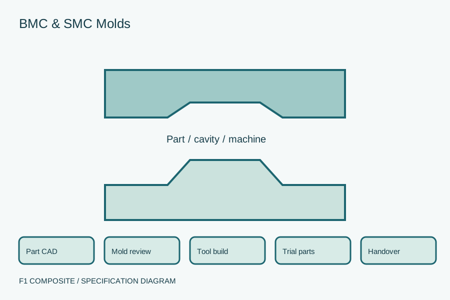
Define matched tooling for BMC or SMC components. Review part geometry, compound, molding-machine interfaces, trial parts and the tooling handover package.
Define the proposed supply package
Equipment, tooling and material sourcing support forms part of F1 Know-How & Services. We review requirements within a technology-transfer, production-setup or improvement engagement.
Agree the exact equipment configuration or material grade, qualification documents, delivery and support responsibilities before ordering. Availability, pricing, lead time and warranty are confirmed for the proposed package.
What to specify and what to request
| Scope | Your specification | Requested supplier response |
|---|---|---|
| Part and compound | Part CAD, critical dimensions, surface and selected BMC/SMC grade | A mold design proposal tied to the intended process |
| Machine interface | Press or injection-machine mounting, operating envelope and heating | Tool dimensions, connections and ejection or handling interfaces |
| Tool lifecycle | Cavity count, expected production duty and maintenance access | Trial criteria, spare components and drawing ownership |
Resolve acceptance before placing an order
CHECK 1
Review manufacturability before cutting steel
The selected compound and molding process influence filling, vents, parting lines and release. Resolve inserts, threads and cosmetic faces during design review.
CHECK 2
Specify trial-part acceptance
Agree the dimensional report, surface criteria and any required material or functional tests. Trial conditions and compound identification should accompany the samples.
CHECK 3
Make changes traceable
Name the party approving design revisions and trial corrections. Include a final drawing set, tool identification, maintenance documents and agreed replaceable components at handover.
Purchasing questions
Is a BMC mold the same as a pultrusion die?
No. BMC/SMC tooling forms discrete molded components; a pultrusion die produces a continuous section. The drawings, machine interfaces and acceptance procedures differ.
Related sourcing specifications
Browse equipment & tooling →Technology transfer & consulting →Profile resin selection →
Discuss BMC & SMC Molds
Share the specification and destination. The next step is to define the equipment or material support needed within your Know-How engagement.
Drawings and technical documents can follow after the initial contact.
- 1Part CAD and inspection drawing
- 2Named BMC/SMC compound and molding process
- 3Molding machine and utility interface data
- 4Expected volume, cavity count and surface requirements
- 5Trial-part acceptance and ownership requirements