Pultrusion Dies & Tooling
Prepare a pultrusion die inquiry with the section drawing, resin system, reinforcement and line interfaces. Define tooling ownership, trial parts and acceptance.
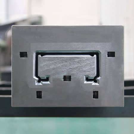
Define the proposed supply package
Equipment, tooling and material sourcing support forms part of F1 Know-How & Services. We review requirements within a technology-transfer, production-setup or improvement engagement.
Agree the exact equipment configuration or material grade, qualification documents, delivery and support responsibilities before ordering. Availability, pricing, lead time and warranty are confirmed for the proposed package.
What to specify and what to request
| Scope | Your specification | Requested supplier response |
|---|---|---|
| Forming geometry | Section dimensions, radii, wall thickness, internal cavities and tolerances | Approved cavity, mandrel and preformer drawings |
| Heating and mounting | Line center height, die envelope, heater and sensor connections | Mounting details and the agreed thermal-control interfaces |
| Tooling package | Die, preformers, mandrels, injection interface and wear parts | A tool list, drawing release process and trial-part inspection plan |
Choose tooling around the profile family
| Module / stage | Define before procurement | Required output / record |
|---|---|---|
| Solid rods and flat strips | Outside size, edge finish and straightness; plan fiber distribution across the section. | Cavity drawing, entry geometry and trial inspection plan. |
| Round, square and shaped tubes | Wall thickness, internal geometry, mandrel support and the fiber path around it. | Mandrel/support drawings, alignment references and access for assembly. |
| I-beams, channels and angles | Web/flange transitions, corner reinforcement and mat placement. | Preformer sequence, critical dimensions and checks for twist or warpage. |
| Sheet piles and interlocking sections | Interlock clearance, wall alignment and repeat assembly fit. | Matched samples and an agreed interlock inspection method. |
| Grating bearing bars and custom profiles | Bearing-bar geometry or the specific shutter/window/industrial section. | Section-specific tooling, surface criteria and mating-part fit checks. |
Preforming, guide plates & mandrel supports
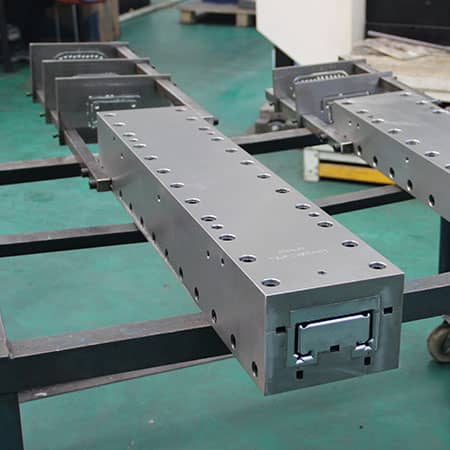
| Module / stage | Define before procurement | Required output / record |
|---|---|---|
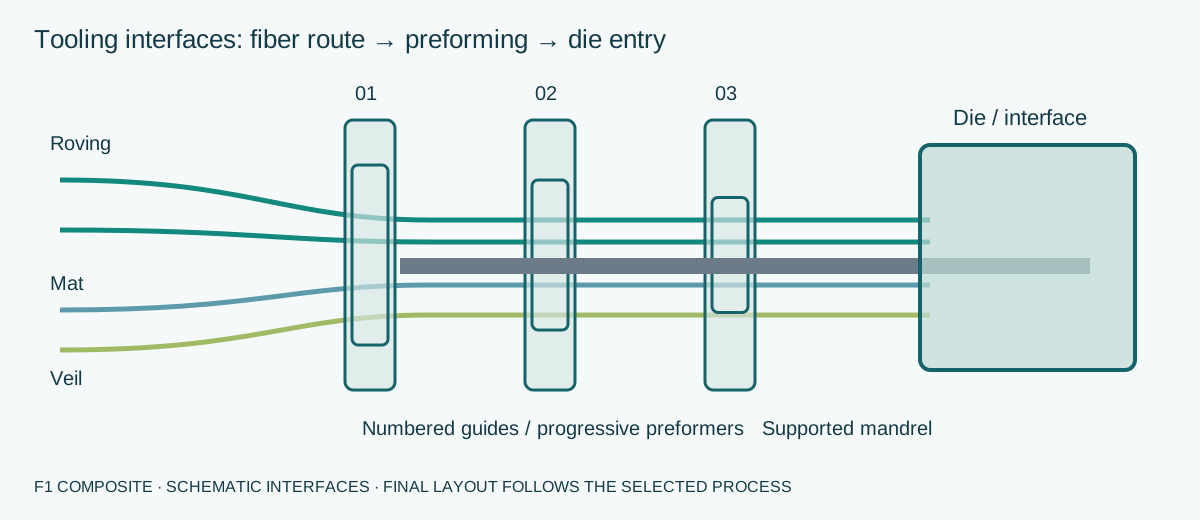
| Creel and fiber guides | Package layout, roving map, guide-hole arrangement and tension-control method. | A numbered routing plan tied to the reinforcement schedule. |
| Mat and veil forming | Slit width, overlaps, orientation and the path around corners and cavities. | A progressive forming sequence and trial checks for wrinkles or displaced layers. |
| Die-entry preform | Transition geometry, entry alignment and access for setup and cleaning. | Preformer drawings, mounting datums and an integrated trial with the die. |
| Hollow-section support | Mandrel supports, thermal movement and fiber passage. | Assembly sequence and clear identification of replaceable or wear components. |
Production fixtures & inspection tooling
| Module / stage | Define before procurement | Required output / record |
|---|---|---|
| Die mounting and alignment | Line center height, mounting envelope and the datums used for setup. | Mounting plates, alignment references and a setting record. |
| Puller contact tooling | Contact length, section support and allowable marking or distortion. | Grip/shoe design matched to the offered puller and representative trials. |
| Cutting and drilling fixtures | Support span, datum faces, hole positions and local edge protection. | Fixture drawing, first-piece inspection and replaceable locating parts. |
| Inspection gauges and spares | Critical-fit dimensions, tool IDs and the approved drawing revision. | Gauge list, calibration requirements and a spare/wear-parts schedule. |
Tool manufacture, trial & handover
| Module / stage | Define before procurement | Required output / record |
|---|---|---|
| Design release | Profile and tooling drawings, steel/surface-treatment proposal and critical interfaces. | Buyer approval before manufacture; no fixed finish or tolerance assumed across all dies. |
| Machining and finish | Dimensional inspection, cavity condition, heater/sensor positions and identification. | Inspection report against the approved tool specification. |
| Trial and correction | Material grades, reinforcement schedule, line configuration and part acceptance. | Traceable trial samples, deviation list and agreed corrective actions. |
| Release to production | Final drawings, parts list, maintenance information and ownership/licensing terms. | Signed handover record with unresolved items and responsible parties. |
Resolve acceptance before placing an order
CHECK 1
Start with the production section
Identify critical assembly dimensions and cosmetic faces. The tool maker must account for the chosen material and process when proposing cavity geometry; the finished-part drawing alone does not define the machining dimensions.
CHECK 2
Resolve closed-section details
Hollow profiles need a coordinated mandrel and support arrangement. Review how fibers pass through the preformers and how the tooling will be assembled, aligned and maintained.
CHECK 3
Protect the handover
Agree ownership, drawing access, permitted use, identification and replacement parts. Define where trials occur, which material is used and how modifications are approved.
Purchasing questions
Does a new die guarantee a finished profile will meet its specification?
Tooling is one part of the process. Geometry, reinforcement, resin and production conditions must be validated together on trial profiles before production release.
Related sourcing specifications
Browse equipment & tooling →Technology transfer & consulting →Profile resin selection →
Discuss Pultrusion Dies & Tooling
Share the specification and destination. The next step is to define the equipment or material support needed within your Know-How engagement.
Drawings and technical documents can follow after the initial contact.
- 1Dimensioned profile drawing and tolerance priorities
- 2Resin, fibers, mat/veil and layup information
- 3Line mounting, heating and injection interfaces
- 4Expected volume and maintenance requirements
- 5Sample inspection criteria and tooling ownership terms