Skip to content
Fabrication guide

FRP profile machining: from cut length to inspected part

Specify cutting, drilling, slots and CNC machining for pultruded fiberglass and GRP profiles. Define the features that control fit, then agree the process and inspection records for your part.

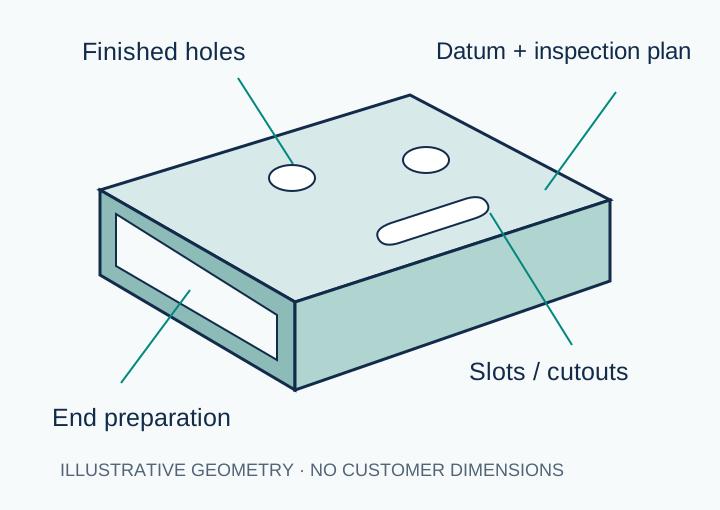
FIG. 1 Machined profile feature mapSchematic · not to scale
Illustrative hollow FRP profile with drilled holes, a routed slot and finished end
Original explanatory drawing. Feature placement does not establish a structural design or an available F1 configuration.
Drawing
Revision + datums
Precision
Feature-specific limits
Release
Agreed inspection

Last updated

Discuss a machining RFQPlan tolerance requirementsWhatsApp

Send your requirements for feasibility review. The drawing and quotation define the agreed supply.

A finished part needs more than a cut length

Machine pultruded fiberglass profiles from a finished-part drawing that defines the material, datums, cut lengths, holes, slots and acceptance criteria. Support the section, control tool wear and heat, inspect entry and exit edges, and agree exposed-edge treatment. Confirm critical tolerances on the proposed material and process before production.

1. The incoming profile

Choose the section and material. Width, wall, straightness and twist affect workholding and the remaining material around a hole or notch.

2. The machined features

Specify finished sizes, locations, angles, depths and edge conditions. Identify the dimensions that control the real assembly.

3. The acceptance record

Agree how the part will be measured, what must be recorded and when a first article or physical fit test is required.

This guide covers glass-fibre pultruded profiles. Carbon-fibre composites, qualified electrical tools, pressure components and complete structural assemblies need their own process and qualification requirements. Use the material SDS, suitable dust extraction, machine guarding and the workshop's applicable exposure controls.

Start with an identified profile and drawing package

Define the material entering the workshop and the finished part leaving it. A drawing list alone cannot establish the geometry or the acceptance criteria.
Profile and units
State the section, material reference, quantity and units. Distinguish nominal raw-profile dimensions from finished cut lengths, hole sizes and other machined features.
Controlled drawings
Provide the actual files and revisions, datum setup, feature coordinates and limits. Identify the mating part or gauge and whether dimensions apply before or after finishing.
Evidence and records
List the material evidence and first-article or production records needed. Confirm applicability to the selected section and formulation, and resolve missing evidence before release.

Round-tube evidence packageSquare / rectangular-tube evidence packageOther material and product references

Six machining operations, with drawing and inspection inputs

Use these cards to prepare a finished-part specification. Tooling and process settings must be selected for the actual resin, reinforcement, wall thickness, geometry and production quantity.
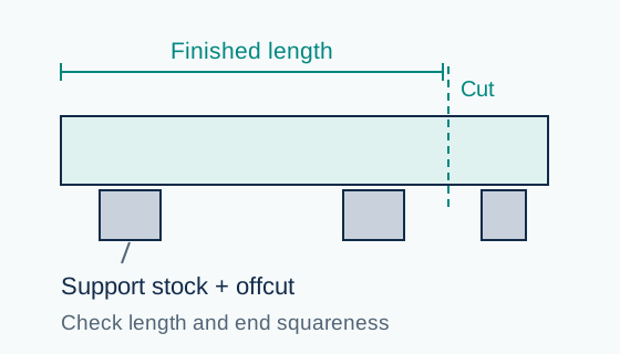
Cut to length & square ends: illustrative feature and support requirements

Operation 1 · schematic, not to scale

Cut to length & square ends

Specify
Finished length, end squareness, reference end, quantity by length and whether dimensions apply after finishing.
Plan the method
Support and restrain the stock and offcut near the cut. Select a blade for the laminate and operation, control feed and heat, and inspect both the cut face and the remaining surface.
Inspect
Measure from the agreed reference end. Check angle, breakout and length after any specified edge preparation.

Stock straightness and twist remain separate requirements; a square saw setup does not straighten the profile.
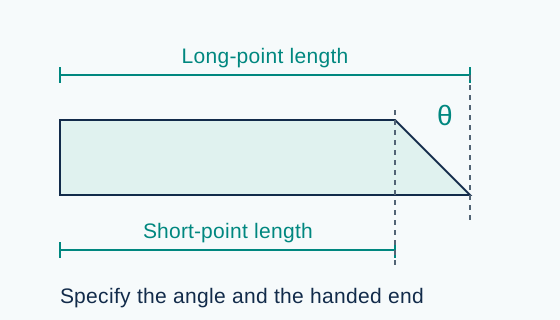
Mitres & angled ends: illustrative feature and support requirements

Operation 2 · schematic, not to scale

Mitres & angled ends

Specify
Cut angle, handedness, long-point or short-point length, matching-part geometry and assembly gap.
Plan the method
Locate the profile consistently and restrain rotation. Trial the end condition with the intended mating geometry before repeating the cut list.
Inspect
Verify the angle and the stated length convention, then inspect the fit against the mating part or approved gauge.

A neat mitre does not establish adhesive-joint or corner-connection strength.

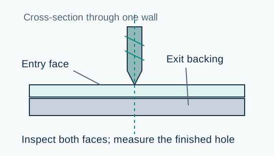
Drilled holes & hole patterns: illustrative feature and support requirements

Operation 3 · schematic, not to scale

Drilled holes & hole patterns

Specify
Finished hole diameter, through or blind depth, location from datums, pitch, orientation and entry/exit acceptance.
Plan the method
Use sharp tooling selected for the material and production quantity. Support the exit with a suitable backing piece where accessible; fixture hollow walls without crushing them.
Inspect
Measure the finished hole and its location. Inspect both faces for breakout and delamination; validate opposite-wall alignment if it controls assembly.

Drill size is a process input, not proof of the accepted hole diameter. Avoid hammer drilling.

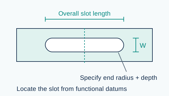
Slots, windows & routed cutouts: illustrative feature and support requirements

Operation 4 · schematic, not to scale

Slots, windows & routed cutouts

Specify
Slot width, overall length, end radius, depth, location, orientation and the minimum material that must remain.
Plan the method
Plan tool access and a supported cutter path. A route may combine drilling and routing; qualify the sequence on the actual section and reinforcement.
Inspect
Check width along the slot, end geometry, location and remaining wall or ligament. Look for heat marks, fibre pull-out and edge damage.

Confirm CNC routing availability for the specific part. Machinability does not establish the residual structural capacity.

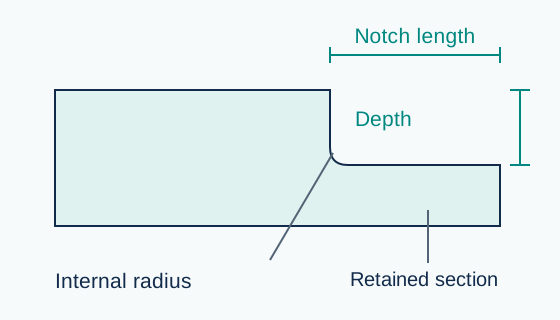
Notches, coping & end relief: illustrative feature and support requirements

Operation 5 · schematic, not to scale

Notches, coping & end relief

Specify
Notch length and depth, internal radii, face identification, orientation and the drawing of the adjoining member.
Plan the method
Review the retained web or flange before selecting the tool route. Support thin features and avoid forcing the tool through the final edge.
Inspect
Check the remaining section, radii and assembly clearance against the released drawing; inspect the ends of the notch for damage.

An engineer must review structural notches and cutouts in the load path. Do not derive a notch size from a photograph.

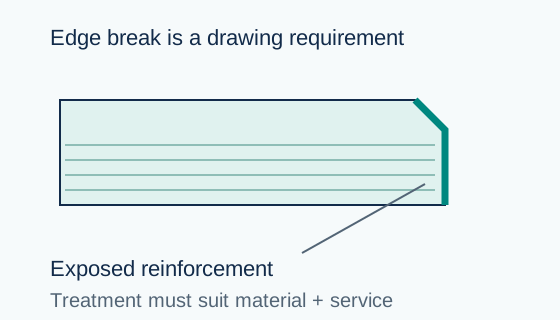
Deburring, chamfers & edge treatment: illustrative feature and support requirements

Operation 6 · schematic, not to scale

Deburring, chamfers & edge treatment

Specify
Permitted edge break, chamfer or countersink geometry, treated surfaces, chemical exposure and final inspection stage.
Plan the method
Remove loose fibres without cutting beyond the drawing limits. Clean and prepare the exposed reinforcement, then apply the agreed compatible sealer or coating where required.
Inspect
Inspect edge condition and treatment coverage. If coating affects a fit, measure in the agreed finished state and observe the specified cure requirements.

Deburring and sealing are separate operations. Sealing does not restore fibres removed by machining or certify the finished component.

Technical basis: Strongwell, Bedford, Exel machining guidance and Fiberline. Their methods and capabilities apply to their stated products; they are not F1 capacity certificates.

Specify the level of dimensional control your assembly needs

The four levels below organize a purchasing brief. They are not standardized precision grades or published F1 capability bands. A tight limit must be agreed for each material, feature and process.

Control level 1

Cut-length parts

A member must fit a defined installation envelope.

Drawing
Length, end angle, reference end, section orientation and raw-profile limits.
Verification
Length and end checks in an agreed support condition; confirm instrument range and sampling.
Release evidence
Approved cut list and visual acceptance examples.

Control level 2

Assembly parts

Holes, slots or reliefs must mate with another component.

Drawing
Feature sizes, locations, mating-part tolerances, clearances and relevant datums.
Verification
Finished-hole or slot gauges plus location checks; an assembly fixture can supplement dimensional inspection.
Release evidence
First article with the mating component or an agreed representative gauge.

Control level 3

Datum-controlled parts

Several features must retain their relationship across a part or batch.

Drawing
Functional datums, individual critical dimensions and any specified geometric tolerances.
Verification
A defined datum setup, appropriate measurement method and recorded results for identified features.
Release evidence
Ballooned drawing, inspection plan and approved first-article results.

Control level 4

Tight-fit or special-function parts

A small clearance, sealing interface or electrical/structural function controls acceptance.

Drawing
Functional limits, mating-part variation, material condition and service requirements.
Verification
Confirm measurement uncertainty and production repeatability for the actual material, fixture and tool route.
Release evidence
Feasibility review and agreed trial/qualification evidence before a production commitment.
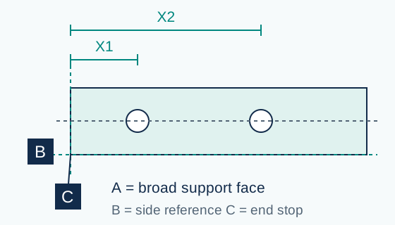
FIG. 2 Locate features from functional datumsSchematic · not to scale
Two holes independently located from end datum C, with a broad support datum A and side datum B
Illustrative datum arrangement only. Define the datum system, contact/support conditions and measurement setup on the released drawing; do not assume these faces suit every section.

Read a tolerance literally

The examples below all use an invented 100 mm nominal dimension. They illustrate arithmetic only. None is a recommended tolerance or an F1 capability claim.

Illustrative dimension limits, not machining grades
Drawing calloutLower / upper limit
100 ±1 mm99–101 mm
100 ±0.5 mm99.5–100.5 mm
100 ±0.2 mm99.8–100.2 mm
100 +0 / −0.1 mm99.9–100.0 mm

A hole's diameter and its position are different characteristics. A ± coordinate tolerance and a geometric position tolerance are also different specifications. For mating parts, review both components' permitted variation and the final coated or sealed state.

Product tolerances remain product-specific: Strongwell explicitly limits its tables to EXTREN. A general note such as “per standard” does not define every machined feature.

Turn a critical dimension into a clear inquiry

Prepare a dimension for your RFQ

Edit the illustrative values to express your required limits in millimetres. This tool calculates a tolerance band; it does not select an industry grade, check a fit or confirm F1 machining capability.

Lower limit
99.5 mm
Upper limit
100.5 mm
Total tolerance band
1 mm

Formula: lower/upper limit = nominal + lower/upper deviation. For example, 100 mm with −0.5 / +0.5 mm deviations gives 99.5–100.5 mm. Geometric position, angular tolerances and measurement uncertainty need separate review.

Include this requirement in an RFQ →

Inspect the feature, the surface and the fit

A first article shows the measured condition of an identified part. Production capability requires evidence of repeatability from the agreed process; neither CNC machining nor a gauge display proves it.

Download the blank first-article inspection template (CSV) to plan the record. It contains no measurements or acceptance decisions; complete it against the identified sample and agreed inspection method.

Machining inspection planning matrix
CharacteristicWhat the drawing must defineInspection plan
Raw profileWidth / OD / ID, wall, straightness, twist and section orientationState support positions, gauge length and datum surfaces. Check the incoming section before adding machined features.
Cut length and endReference end, length convention, angle and end conditionUse a suitable length/angle method with the part supported as specified. Record the final state after required finishing.
Hole diameterFinished bore size, through or blind depth, opposite-wall alignmentChoose a bore measurement or calibrated GO/NO-GO gauge appropriate to the feature. Caliper access and display resolution alone do not validate the method.
Hole / slot locationFunctional datums, coordinates, pitch and any geometric toleranceReproduce the datum setup. Use a suitable fixture or coordinate measurement method; record which faces establish the reference.
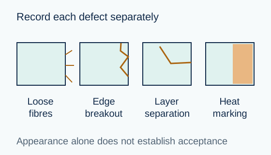
Machined surfaceLoose fibres, edge breakout, layer separation, resin damage and treatmentAgree visual examples and any numerical defect limits. Measure defects with a suitable method; assess dimensional and visual acceptance separately.
Fit and traceabilityCounterpart revision, gauge ID, part / lot identity and inspection stageIf required, perform the physical assembly check and record the counterpart or gauge. A digital model or a photograph does not replace a specified fit test.
FIG. 3 Keep defect categories separateSchematic · not to scale
Four schematic defect types: loose fibres, edge breakout, layer separation and heat marking
Exaggerated visual examples. Actual defect definitions and permissible limits belong in the approved inspection plan.

Record actual values, with enough context

A useful first-article sheet identifies the part, material or lot, drawing revision, ballooned feature, required limits, measured value, instrument or gauge, support condition, inspection date and acceptance decision.

Agree sampling and record requirements for production. Repeat the relevant checks after a tooling, fixture, program, material or process change that can affect the feature. Hold nonconforming parts for the agreed disposition; rework or repair needs approval where it can affect fit or function.

Use the inspection-record checklist →

From drawing review to a labeled machining kit

This is a proposed procurement workflow. The quotation and approved documents confirm which operations, trials, records and packing controls are included.
  1. STEP 1

    Resolve the document package

    Check the drawing list against the actual files, revision and purchase scope. A manufacturing requirements file that lists drawings is not a substitute for those drawings. Resolve missing coordinates, datums and precedence before release.

  2. STEP 2

    Review manufacturability

    Check material, raw-profile variation, tool access, support, wall compression, cutouts and mating clearances. Confirm the machining route and any external processing.

  3. STEP 3

    Approve the first article

    Agree critical dimensions, inspection method, acceptance limits, edge condition and any physical fit check. Resolve deviations before the production run.

  4. STEP 4

    Control the production run

    Keep setup and revision records, monitor tool condition and check the agreed features at the specified frequency. Separate accepted, held and reworked parts.

  5. STEP 5

    Identify and protect parts

    Match part labels, cut-list quantities and any color codes to the assembly schedule. If a color band is specified, agree adhesion, visibility, durability, cure and inspection requirements.

  6. STEP 6

    Release the package

    Reconcile quantities and records, protect machined ends and holes, prevent long-profile distortion, and identify the bundle sequence. Send the agreed inspection and packing documents.

Example: preparing a drilled tube-frame kit

For a hypothetical frame with multiple tube lengths, start with one controlled cut list and a drawing for each hole pattern. Identify the mating connector and critical clearance; keep raw tube size limits separate from hole-size and hole-location limits. Confirm a first-article fit check, then agree part labels, bundle sequence and the inspection records to accompany the shipment. This is a planning example, not a completed-project claim.

Machining and tolerance questions

Can pultruded fiberglass profiles be CNC machined?

CNC drilling and routing are used in the composites industry for repeat features and cutouts. For an F1 inquiry, provide the section, material, drawing, quantity and critical requirements so the machining route, tool access, fixture and supplier capability can be confirmed. CNC equipment alone does not establish a tolerance guarantee.

What machining tolerance can F1 guarantee?

There is no single tolerance for every FRP material, length or feature. Send the finished-part limits and datums. F1 confirms feasibility, the inspection method and the agreed production requirements for the proposed part. The planning examples on this page are buyer requirements, not published F1 capability ratings.

Is the raw pultrusion tolerance the same as the hole-position tolerance?

No. The raw profile has its own width, wall, straightness and twist requirements. A machined hole adds a finished diameter and a location relative to chosen datums. Both sets of requirements must be compatible with the mating part and the inspection setup.

Do all cut edges and drilled holes need the same sealant?

No. Agree exposed-edge treatment for the resin, environment, mating surfaces and required function. Chemical exposure can make protection particularly important. The approved sealer or coating instructions control preparation and cure; sealing does not replace a structural or electrical qualification.

Should I specify ISO 2768 or a universal precision grade?

Do not assume a generic tolerance note covers every FRP feature. If a general-tolerance standard is required, identify its exact part, edition and class, confirm that it applies, and state individual limits for critical features. Define the datums, surface condition and inspection method on the approved drawing.

What should accompany a machined-profile RFQ?

Send the profile and material reference, drawing revision and units, cut list and quantities, feature schedule, mating-part information, critical dimensions and datums, exposed-edge treatment, first-article requirements, inspection records and part-label or packing needs. Identify whether the request is for trial pieces, a first article or production.

Technical sources and scope

This guide synthesizes representative manufacturers' public fabrication guidance. Source-specific tolerances, machinery, certifications and production claims remain with their original suppliers. All drawings on this page are original explanatory schematics.

Send the part requirements that control fit

Share the profile, material, drawing revision, cut list, hole and slot schedule, critical tolerances and inspection needs. Use the tolerance planner to carry a dimension and its limits into the RFQ, then add the remaining drawing and order requirements. We will review what requires a trial or additional evidence. We reply within one business day.

Get a quoteWhatsApp