C-shape cover
Reference: D × T
- 20 × 3 mm
- 25 × 3 mm
- 30 × 3 mm
- 35 × 3 mm
Industrial fixed FRP / GRP ladder assemblies with pultruded side rails, fluted rungs, mounting brackets, optional cage components and separate C/U rung-cover retrofits. Nominal catalog dimensions are shown below; the approved project drawing controls fabrication and fall-protection interfaces.
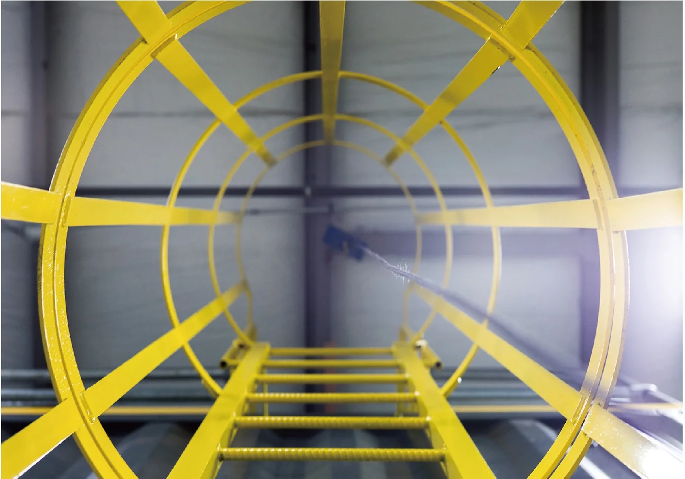
The assembly combines square pultruded side rails, fluted round rungs, rung gaskets, splice bars and project-specific wall or floor brackets. Optional hoops and cage strips form one access-safety arrangement; a vertical ladder-safety or personal-fall-arrest interface may still govern under the adopted standard.
This product page owns the fixed industrial ladder intent. For platform-edge protection, use the separate fiberglass handrail and guardrail systems page; for walking surfaces, use FRP stair treads or grating.
| Component / parameter | Nominal catalog value |
|---|---|
| Maximum length without a splice | 7,300 mm |
| Maximum ladder length with catalog cage | 10,200 mm |
| Outside width, rail to rail | 500 mm |
| Rung spacing, center to center | 300 mm |
| Fluted round-tube rung | 32 mm outside diameter × 6.4 mm wall |
| Square-tube side rail / post | 50.8 × 50.8 × 6.4 mm |
| Solid square splice bar | 38 × 38 mm × 200 mm long |
| Rung gasket | Black rubber |
| Catalog rung-to-rail rivet | 4 × 20 mm |
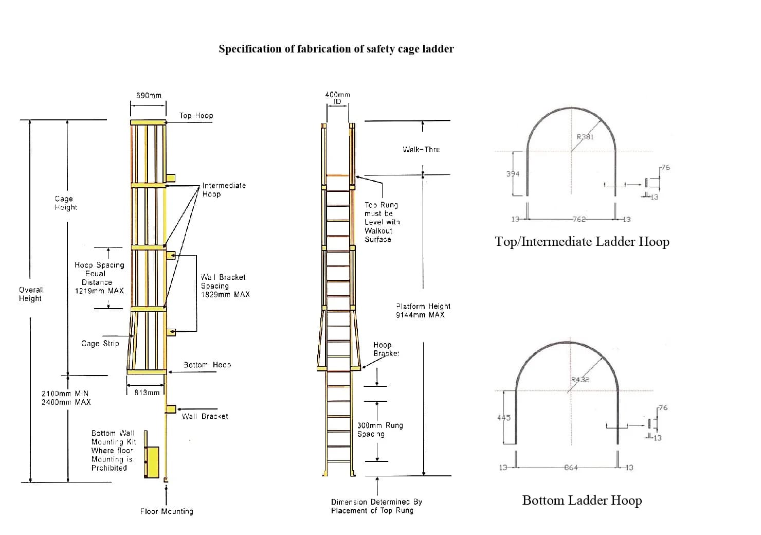
| Component / parameter | Nominal catalog value |
|---|---|
| Ladder hoop | 76 mm wide × 13 mm thick; hand lay-up; predrilled with bolt assemblies |
| Hoop thickness source check | English table and section detail show 13 mm; the Chinese line shows 10 mm — approved drawing controls |
| Hoop bracket | 75 × 140 × 10 mm U-shape; predrilled with bolt assemblies |
| Cage strip | Pultruded C-channel 50 × 14 × 3 mm |
| Wall-mount bracket | Pultruded angle 76 × 200 × 9.5 mm; 457 mm long |
| Floor mount | Pultruded angle 102 × 102 × 9.5 mm; two per set with bolt assemblies |
| Optional foot-base mount | Molded BMC base |
| Component / parameter | Nominal catalog value |
|---|---|
| Equal hoop spacing | 1,219 mm maximum |
| Wall-bracket spacing | 1,829 mm maximum |
| Bottom-of-cage clearance | 2,100 mm minimum / 2,400 mm maximum |
| Front cage width | 813 mm |
| Walk-through side clear dimension | 400 mm ID |
| Top-rung transition | Top rung level with walkout surface |
| Catalog platform-height reference | 9,144 mm maximum |
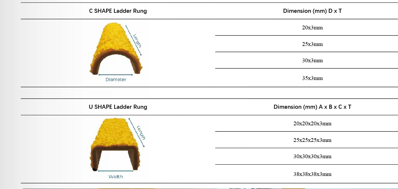
Reference: D × T
Reference: A × B × C × T
State vertical rise, lower and upper landing levels, step-across or walk-through exit, available wall stand-off and all nearby obstructions.
Name the jurisdiction, owner specification and fixed-ladder standard. Cage, ladder-safety and personal-fall-arrest requirements are not interchangeable.
Identify concrete, steel, masonry or FRP framing, plus edge distances and access behind the support. The substrate controls bracket and anchor design.
List chemicals, concentration, temperature, washdown, UV and electrical exposure so the resin, surface and metal hardware can be selected for the service.
Confirm whether the design needs a cage, vertical ladder-safety system, personal fall-arrest interface, rest platform or a combination under the adopted rules.
Approve the elevation, bracket schedule, splice locations, top transition, rung arrangement, anchor schedule and bill of materials before fabrication.
Safety-standard checkpoint. For U.S. general industry, review OSHA 1910.23 and OSHA 1910.28. For permanent access to machinery, confirm whether ISO 14122-4:2016 is within scope. Catalog cage dimensions do not themselves establish compliance.
This page covers permanently mounted industrial fixed ladders assembled from FRP side rails, fluted rungs, brackets and optional access-safety components. It does not cover consumer step ladders, extension ladders or FRP cable-ladder trays.
The source catalog lists 500 mm outside rail-to-rail width, 300 mm rung spacing, 32 mm outside-diameter fluted rungs with 6.4 mm wall, and 50.8 × 50.8 × 6.4 mm square side rails. These are catalog references; the approved project drawing controls the released geometry.
Not automatically. The required system depends on ladder height, installation date, jurisdiction and owner standard. For U.S. general-industry fixed ladders extending more than 24 ft, OSHA 1910.28(b)(9) addresses ladder-safety or personal-fall-arrest systems; a cage may coexist but must not be treated as a universal substitute. Confirm the adopted rule before release.
It can be evaluated when the RFQ identifies the applicable standard and supplies the full access geometry, support substrate, fall-protection concept and load basis. The catalog dimensions alone are not a compliance certificate, and ISO 14122-4 specifically addresses permanent access to machinery within its stated scope.
They are thin gritted covers fitted over existing steel or timber rungs. They are separate from the complete ladder's 32 mm fluted FRP tube rung and do not establish a whole-ladder load rating. Adhesive, substrate preparation and slip-test requirements must be specified for the retrofit.
Send the vertical rise, clear width and stand-off, top-exit detail, wall or frame substrate, bracket locations, exposure, governing standard, cage or fall-protection concept, color, quantity and destination. A marked elevation or CAD file is the fastest route to an approved BOM and fabrication drawing.
Send the ladder elevation, the supports, the governing standard and the destination. We reply within one business day; a formal quotation follows once the specification and delivery are reviewed.