FRP grating is easy to handle and forgiving to cut, which is part of why it is chosen. Most installation problems still come from a handful of avoidable decisions: supports that are not level, panels laid the wrong way round, too few hold-downs, and cut edges left open. This guide walks through an installation in the order a crew meets those decisions.
Before the panels arrive
Work from the approved layout drawing. It should show every panel mark, the span direction, cut-outs for pipes and equipment, the support members and the clip positions. Check the support steel or concrete against it: supports level and coplanar, spacing no wider than the span the grating was selected for, and flanges wide enough to give the required bearing. A support that is out of level by a few millimeters turns into a rocking panel and a trip edge.
Keep molded and pultruded panels apart in storage and on the drawing. They use different clips, and pultruded panels have a direction.
Orientation and bearing
Pultruded grating spans one way. Its strength comes from bearing bars joined by cross rods, so the bearing bars must run between the supports. Laid the other way, the panel is carried by the cross rods and will not perform to its load table.
Molded grating spans two ways with square mesh, which makes it tolerant of cut-outs and irregular layouts. Rectangular-mesh molded panels still have a stronger direction, so follow the drawing.
Bearing. A common starting value is at least 38 mm (1.5 in) of bearing on each support. Panel edges at cut-outs, trenches and penetrations need their own support: add trimmer angles or support frames rather than leaving an edge cantilevered.
Hold-down clips
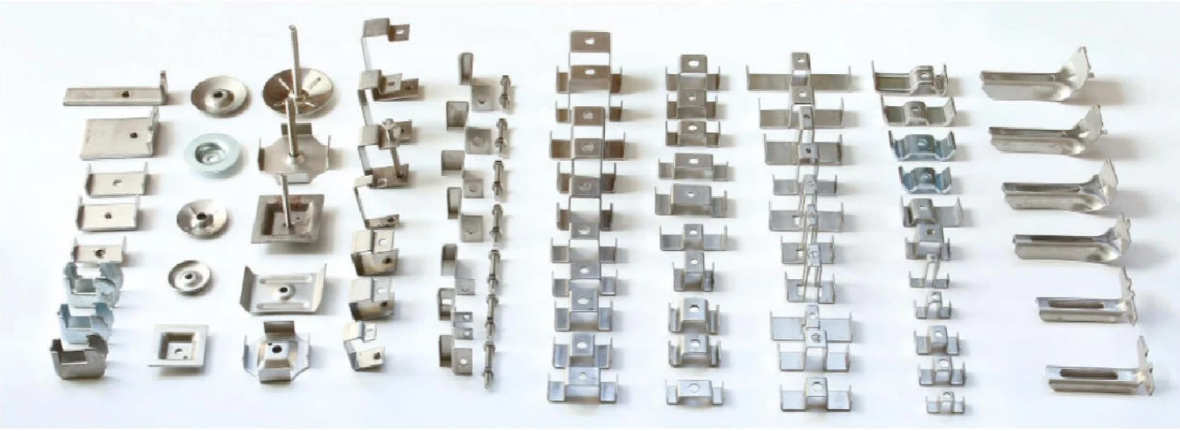
F1's clip layout guidance gives these starting values for coordination, before the project drawing fixes the final design:
| Location | Starting value |
|---|---|
| Each panel | At least 4 panel-to-support hold-downs |
| Each support line | At least 2 panel-to-support hold-downs |
| Along a support | No more than 1,200 mm (4 ft) between hold-downs |
| Molded panel joints | C connectors typically every 600 to 900 mm (2 to 3 ft) |
| Bearing at support | At least 38 mm (1.5 in) |
Clip letters are not standardized between manufacturers, so select by function:
| F1 clip | Function | Grating family |
|---|---|---|
| M hold-down | Seats across two adjacent bars and holds the panel to its support | Molded and pultruded |
| J support-hook clamp | Clamps the panel to a support flange from below, without drilling the support | Molded and pultruded |
| C panel connector | Aligns adjacent molded panel edges; it does not replace support or a hold-down | Molded |
| T clip | Series-specific hold-down for selected F1 pultruded bearing-bar series | Pultruded |
The F1 clips are 316 stainless steel. Tighten fasteners to the value on the drawing, and add hold-downs where wind, vibration or vehicle traffic act on the panels. Details for each family are on the molded grating and pultruded grating pages, with DXF drawings of the clips.
Cutting and sealing
Cut with carbide- or diamond-tipped blades on a circular saw, grinder or jigsaw, with dust extraction, a suitable respirator, eye protection and covered skin. Plan cuts so that cut bearing-bar ends of pultruded panels land on a support or on added framing.
Cutting exposes glass fibers. Grind the cut smooth and seal every cut surface with a resin compatible with the grating resin, as supplied or specified by the manufacturer. Sealing keeps moisture and chemicals from wicking along the fibers and protects the edge from UV. After cutting, recheck the hold-down layout: a cut-out often removes the clip position the drawing relied on.
Inspection after installation
Walk the finished area. Look for rocking or springy panels, loose or missing clips, height steps between panels that create a trip edge, damaged grit surfaces and unsealed cuts. OSHA 1910.22 requires walking-working surfaces in general industry to be kept free of hazards such as sharp or protruding objects, loose boards and spills, and to be inspected regularly, so add the grating to the site's inspection routine.
Marine and offshore projects
ASTM F3059 sets testing and performance requirements for FRP gratings used in marine construction and shipbuilding, as an equivalency to steel gratings rated for up to 94 lbf/ft² (4.5 kN/m²). Its tests cover deflection, assembled grating ultimate failure, wheel loading, impact, skid resistance, durability, UV, salt spray, surface flammability and structural fire integrity under ASTM E119 exposure; it does not address hydrocarbon pool or jet fires. The flag state or class society decides which fire category applies on a given deck.
To choose the grating itself, compare molded and pultruded fiberglass grating and check spans with the load table guide.
FRP grating installation questions
How many clips does an FRP grating panel need?
A common starting layout is at least four panel-to-support hold-downs per panel, at least two on each support line and no more than 1,200 mm (4 ft) apart along a support. Long panels, wind, vibration and traffic can require more. The approved project drawing sets the final count and spacing.
Do cut edges of fiberglass grating need sealing?
Yes. Cutting exposes glass fibers. Seal every cut surface with a resin compatible with the grating resin, as supplied or specified by the manufacturer, especially in chemical, marine and outdoor service.
What tools cut FRP grating?
Circular saws, grinders or jigsaws fitted with carbide- or diamond-tipped blades. Use dust extraction, a suitable respirator, eye protection and covered skin, because glass and resin dust irritates.
Can molded and pultruded grating use the same clips?
Some clip types fit both, others fit only one. In F1's range the M hold-down and the J support-hook clamp are listed for both families, the C connector for molded panels only and the T clip for specific F1 pultruded series. Match the clip to the exact series and bar geometry.