Pullwinding Equipment
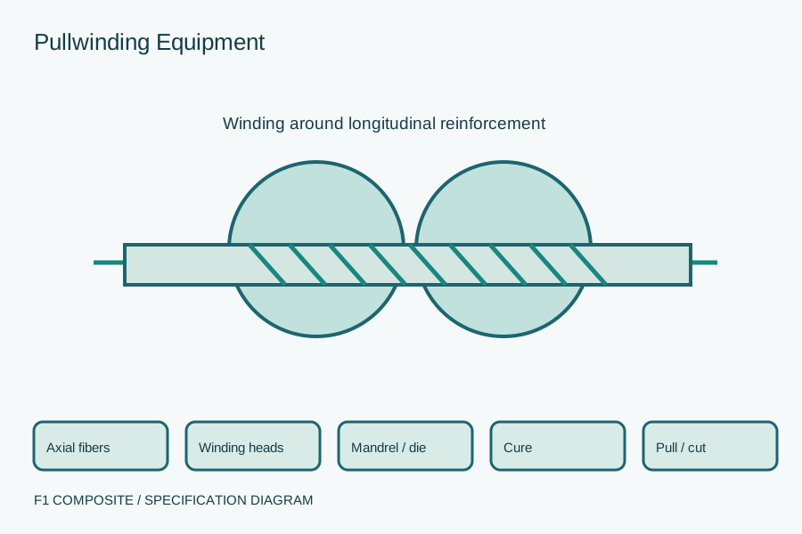
Define a pullwinding line for composite tubes with longitudinal and wound reinforcement. Coordinate the mandrel, winding heads, resin system and pulling controls.
Define the proposed supply package
Equipment, tooling and material sourcing support forms part of F1 Know-How & Services. We review requirements within a technology-transfer, production-setup or improvement engagement.
Agree the exact equipment configuration or material grade, qualification documents, delivery and support responsibilities before ordering. Availability, pricing, lead time and warranty are confirmed for the proposed package.
What to specify and what to request
| Scope | Your specification | Requested supplier response |
|---|---|---|
| Tube definition | Inner and outer geometry, material and required laminate architecture | A proposed tooling and reinforcement arrangement |
| Winding module | Fiber feeds, winding directions and line coordination | A control and tension-management proposal for the specified layup |
| Line integration | Mandrel, impregnation, curing, pulling and cutting | A complete interface list and trial plan |
Mandrel, winding & pulling integration
| Module / stage | Define before procurement | Required output / record |
|---|---|---|
| Fiber supply | Axial reinforcement and winding packages, tension and replacement access. | Fiber-route and creel layouts. |
| Mandrel and winding | Tube section, winding directions, intended architecture and motion coordination. | Tooling/control proposal with the responsible integrator identified. |
| Cure and downstream | Resin delivery, heated tooling, pulling, cooling and cutting. | A representative tube trial and documented acceptance results. |
Resolve acceptance before placing an order
CHECK 1
Separate the process from the rating
Adding wound reinforcement changes the laminate architecture. Any pressure, torsion or structural duty must be specified and verified on the finished tube; the equipment description is not a tube performance rating.
CHECK 2
Coordinate motion and reinforcement
Identify the winding pattern, longitudinal reinforcement and process constraints. The supplier must show how winding and pulling are coordinated through the intended operating range.
CHECK 3
Define representative trials
Use the intended resin and reinforcement during acceptance. Agree how tube geometry, laminate condition and required product properties will be inspected, with records supplied at handover.
Purchasing questions
Is pullwinding interchangeable with ordinary pultrusion?
The processes share some line functions, but pullwinding adds controlled wound reinforcement and associated tooling and motion requirements. Confirm that the proposed line supports the actual laminate and geometry.
Related sourcing specifications
Browse equipment & tooling →Technology transfer & consulting →Profile resin selection →
Discuss Pullwinding Equipment
Share the specification and destination. The next step is to define the equipment or material support needed within your Know-How engagement.
Drawings and technical documents can follow after the initial contact.
- 1Tube dimensions, lengths and expected output
- 2Required reinforcement architecture and fiber types
- 3Intended tube duty and product acceptance criteria
- 4Mandrel and existing line details, if upgrading
- 5Factory utilities, destination and training scope