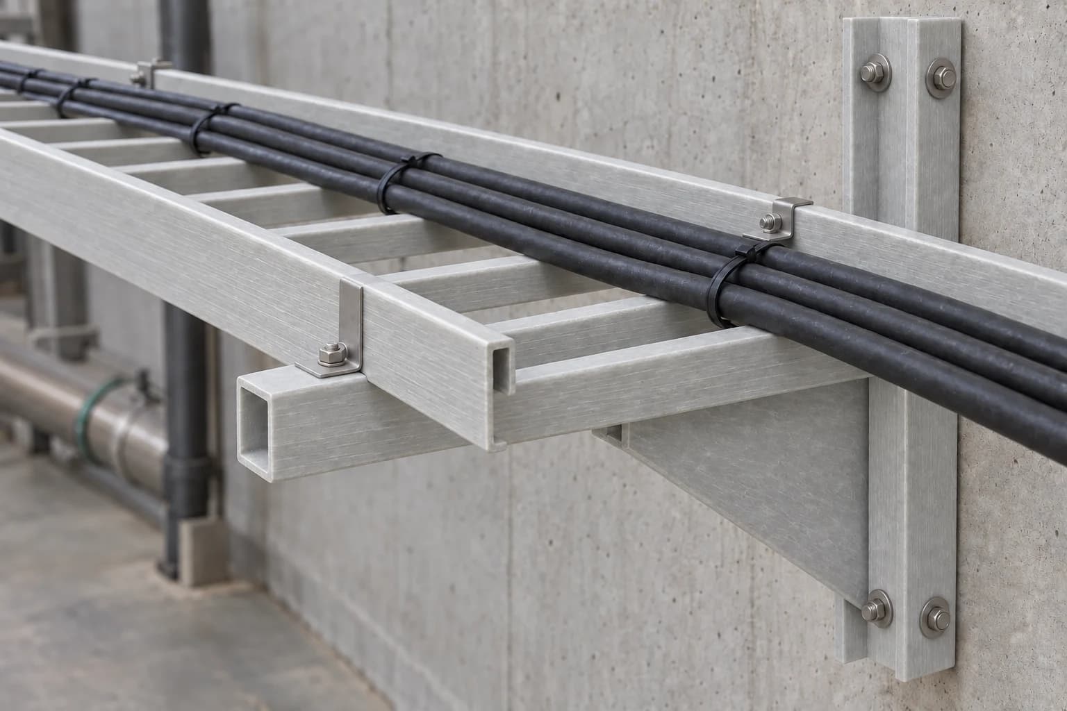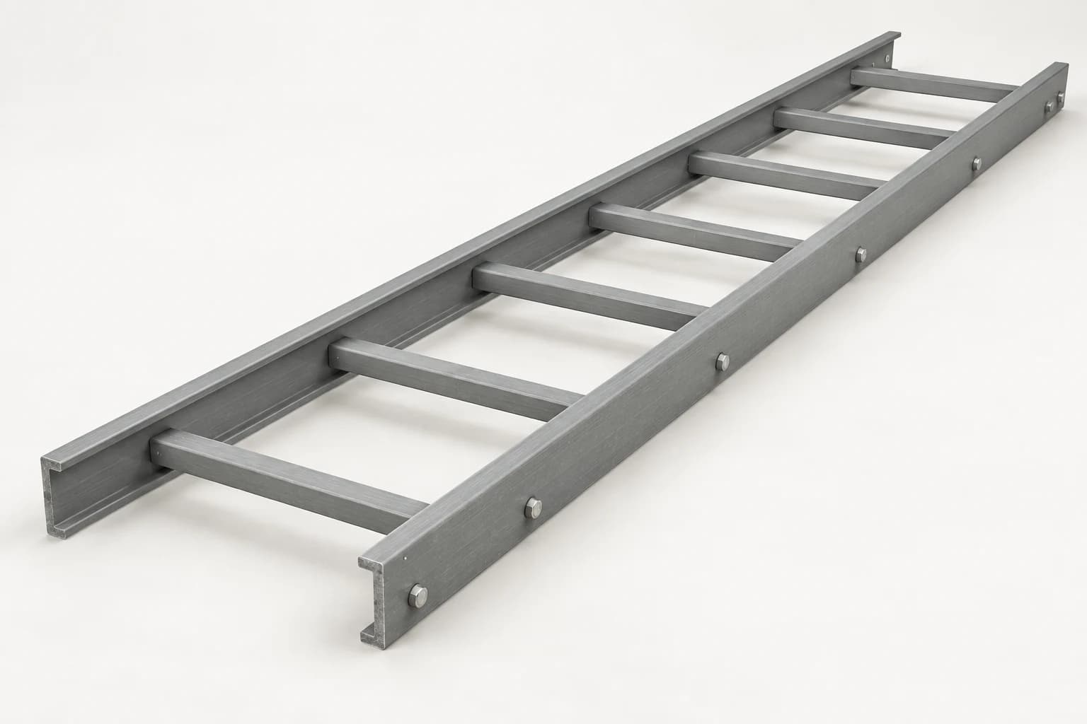
An FRP cable tray or cable ladder is light enough for two people to lift into place, which makes it tempting to install it like any other tray. The material does change a few things. It does not conduct, it expands at its own rate, its cut edges need sealing, and its load table assumes a particular support layout. This guide goes through an installation in the order a crew meets those decisions. Where the supplied system's instructions differ, they govern.
Before the first support goes up
Work from the approved route drawing: support positions, fitting schedule, elevations, cable entry points and the fixings into the supporting structure. Check the drawn support spacing against the load table of the system actually supplied, using the full cable load: the cable schedule's mass per metre, a future allowance, and concentrated loads such as junction boxes hung from the tray.
A load table is only valid under its own conditions. Øglænd, for example, notes that the IEC 61537 load data for its FOE ladder assume an end span of three-quarters of the support spacing, with no splice in the end span. FRP also loses stiffness and strength as its temperature rises, so runs near hot process equipment or in strong sun need the manufacturer's elevated-temperature derating.
Keep the tray, ladder, fittings and hardware of one system together. Splice plates, clamps or fittings borrowed from another supplier change the tested assembly.
Supports, splices and fittings
NEMA VE 2, the industry installation guideline written around metal cable tray, sets out layout rules that FRP manufacturers use as well:
| Item | Layout rule | Source |
|---|---|---|
| Support span | From the load table, and no longer than one straight section, so no more than one splice falls between supports | NEMA VE 2 |
| Splice location | About a quarter of the span from a support; never over a support or at midspan | NEMA VE 2 |
| Horizontal fittings | A support within 600 mm (2 ft) of each end of the fitting | NEMA VE 2 |
| 90° horizontal elbows | An extra support at the 45° point of the arc | NEMA VE 2 |
| Expansion splices | A support within 600 mm (2 ft) of each side | Cable Tray Institute |
| Vertical runs | Cables fastened to the rungs or other transverse members | NEC 392.30(B)(1) |
Why a quarter of the span. A splice is more flexible than the straight section it joins. In a continuous run, the bending moment is largest over the supports and at midspan and close to zero near the quarter points, so a splice there carries little bending and adds the least deflection. With 3 m (10 ft) sections on a 3 m span, the splice sits about 750 mm (2.5 ft) from the nearest support.
Fittings. Elbows, tees and reducers do not carry load the way straight sections do, so VE 2 supports them close to their ends, as in the table. For vertical bends, tees and crosses, follow the supplier's support diagram.
Fasteners and clamps. Use the splice plates, bolts and clamps supplied with the system, in FRP, stainless steel or another material chosen for the environment, and tighten them to the supplier's values. Steelwork torque values can crush the laminate or split a rail around the bolt hole.
Thermal expansion
Every tray material changes length with temperature. NEC 392.44 calls for expansion splice plates where they are needed to compensate for thermal expansion and contraction, and how often depends on the material and the temperature range. For metal tray, the NEMA VE 1 table referenced by the Cable Tray Institute puts an expansion joint every 128 ft (39 m) for steel and every 65 ft (19.8 m) for aluminum at a 100 °F (56 °C) temperature differential. FRP systems have their own spacing, based on the coefficient of thermal expansion in the manufacturer's data.
The length change is easy to estimate: coefficient × run length × temperature range. With an assumed coefficient of 9 × 10⁻⁶ per °C, a 40 m straight run that sees a 50 °C swing between a winter night and summer sun changes length by 40,000 mm × 0.000009 × 50 = 18 mm. Use the value for the supplied laminate, because it depends on the fiber content and direction.
Setting the gap. Each expansion gap is set for the temperature on the day of installation: nearly closed if the tray goes in at the hottest expected temperature, nearly fully open at the coldest, and in proportion between. NEMA VE 1 gives a nomograph for metal tray; the FRP supplier gives its own setting.
Anchors and guides. Between two expansion splices, anchor the tray with hold-down clamps at the support nearest the midpoint, and hold it at every other support with expansion guides that let it slide. Put a support within 600 mm (2 ft) of each side of every expansion splice. A tray clamped tight at every support cannot move, so the expansion goes into bowing or into the splices instead.
Cutting, drilling and sealing cut edges
Field cuts and holes are normal, but they expose glass fibers. Use carbide- or diamond-edged saw blades and carbide-tipped drill bits, with dust extraction, a suitable respirator, eye protection and covered skin. Enduro's installation guide calls for sealing exposed cut surfaces: use the sealing resin or coating supplied or specified by the tray manufacturer, so the cut edge keeps the chemical and UV protection of the rest of the section. Deburr cuts before any cable goes in.
Grounding and bonding
FRP does not conduct, so an FRP tray cannot be part of the grounding path. In the US, NEC 392.60 lets qualifying metal cable tray serve as an equipment grounding conductor; a nonmetallic tray cannot. The grounding path comes from cables that contain their own equipment grounding conductor, or from a separate equipment grounding conductor run in or on the tray. Where NEC 392.10(B)(1) applies, in industrial establishments whose cable tray is serviced only by qualified persons, a single conductor used as an equipment grounding conductor in the tray must be 4 AWG or larger.
Metal parts such as brackets, clamps and support steel still need bonding where the electrical design requires it. Outside the US, apply the local wiring rules, such as the national adoption of IEC 60364. An insulating tray also does not screen electromagnetic interference; the cable tray, trunking and ladder comparison covers EMC and earthing in more detail.
Pulling and securing cables
Set out rollers along straight runs, and radius rollers or sheaves at bends, before the pull starts, so that cables do not drag over rungs, side rails or splice plates. The cable manufacturer sets the pulling tension, bending radius and sidewall pressure limits; place rollers and sheaves to stay within them.
In vertical runs, fasten the cables to the rungs (NEC 392.30(B)(1)), and support cables where they leave the tray for conduit or equipment. For power circuits that must stay restrained under short-circuit forces, use cable cleats tested to IEC 61914 for the declared fault current. The tray's load rating covers the weight of the cables, not fault forces on the cleats.
Covers, outdoor runs and fire stops
Covers protect cables from falling objects, sunlight and weather. Outdoors, fasten them with the cover clamps specified for wind, because a loose cover acts like a sail. A continuous solid cover also traps heat: NEC 392.80(A)(1)(b) limits multiconductor cables to 95 percent of their table ampacity where a tray is covered for more than 1.8 m (6 ft) with solid unventilated covers. Check with the electrical designer before adding covers that were not in the design. For sun-exposed runs, ask the supplier which UV protection the tray carries, such as a surface veil, UV-stabilized resin or a coating.
NEC 392.100 requires nonmetallic cable tray to be made of flame-retardant material. Where a tray passes through a fire-rated wall or floor, NEC 300.21 requires the penetration to be firestopped by an approved method that keeps the fire rating, and the firestop system has to be approved for the tray material and the cables it carries.
Not a walkway. Cable trays and cable ladders carry cables. Mita's installation guidelines and Enduro's instructions both warn against using them as walkways or climbing ladders, so plan access platforms and fall protection separately.
Inspection at handover
Before the cables are energized, walk the route. Check that supports sit at the drawn positions, splices are at the right points and fully bolted, expansion gaps are set and guides are free to slide, and hold-down clamps are on the anchor supports. Fittings should be supported at both ends, cut edges sealed, cables fastened in vertical runs, the grounding conductor continuous and bonded, covers clamped and firestops complete.
Record the installed configuration and the load allowance, so later cable additions can be checked against it. Then add the route to the site's inspection routine: loose fasteners, cracked or crushed rails, chalking from UV exposure, missing clamps and cables added beyond the recorded allowance.
Planning an FRP cable route
To choose between tray and ladder, and between FRP and metal, read the cable tray, trunking and ladder comparison and the specification guide. F1 supplies FRP cable trays and cable ladders with supports and fittings against a route drawing. Send the cable schedule, support spacing, exposure and standards through that page; the offered system's load data and installation requirements are confirmed in the quotation.
FRP cable tray installation questions
How far apart should FRP cable tray supports be?
As far as the offered system's load table allows for the actual cable load, including future cables and any concentrated loads, and no farther than one straight section, so that only one splice falls between supports. Read the table's conditions too. Øglænd, for example, states that its IEC 61537 load data assume an end span of three-quarters of the support spacing with no splice in it.
Where should splices go on an FRP cable tray?
About a quarter of the span from a support, which is where NEMA VE 2 places them to keep bending and deflection at the joint low. Avoid splices over supports and at midspan, and use the splice plates and fasteners supplied with the system, tightened to its instructions.
Can an FRP cable tray be used as an equipment grounding conductor?
No. In the US, NEC 392.60 lets only qualifying metal cable tray serve as an equipment grounding conductor. With FRP, the grounding path comes from cables that contain their own grounding conductor or from a separate equipment grounding conductor run in or on the tray. Outside the US, follow the local wiring rules.
Does FRP cable tray need expansion joints?
Long straight runs with large temperature swings do. NEC 392.44 requires expansion splice plates where they are needed to compensate for thermal expansion and contraction. Their spacing comes from the manufacturer's data and the expected temperature range, and each gap is set for the temperature on the day of installation.