An FRP handrail arrives as tubes, fittings, kick plates and bases, and it becomes a guardrail on site. The material is easy to cut and light to carry, so most installation problems come from somewhere else: posts set out of plumb, bases fixed with the wrong anchors, fittings loaded before the adhesive has cured, and cut ends left open. This guide follows an installation in the order a crew meets those decisions. It draws on the US Department of Defense guide specification for FRP railings, UFGS 06 82 14 (August 2023), and on the catalog data for F1's square- and round-tube systems. The system's own instructions and the approved drawing govern.
Start from an approved layout drawing
The drawing should show every post position, the rail heights, splices, corners and returns, gates, stair sections, kick plates, base types and the anchor schedule. UFGS 06 82 14 asks for installation drawings that show anchorage and the relation to the building construction, with structural analysis signed and sealed by the responsible engineer. The drawing is also where the governing standard enters: OSHA 1910.29 in US general industry, the IBC for buildings, or EN ISO 14122-3 for permanent access to machinery. Our guardrail requirements guide compares their heights, loads and openings.
For design loads, UFGS 06 82 14 follows the IBC and ASCE 7: top rails and handrails carry 50 lbf/ft or a 200 lbf concentrated load in any direction, not at the same time, and guard infill carries 50 lbf on one square foot or 25 lbf/ft² applied horizontally.
Post spacing, heights and tolerances
Post spacing comes from the system and the loads, and the references differ:
| Item | Reference value | Source |
|---|---|---|
| Post spacing | 1,500 mm maximum | F1 square- and round-tube catalog layouts |
| Post spacing | 72 in (1.83 m) maximum | UFGS 06 82 14 |
| Stanchion spacing, machinery access | 1,500 mm maximum | EN ISO 14122-3 |
| Handrail height | 1,220 mm maximum | F1 catalog layouts |
| Top rail height, US general industry | 42 in (107 cm), plus or minus 3 in | OSHA 1910.29 |
| Posts plumb | Within 1/16 in in 3 ft (1.6 mm in 0.91 m) | UFGS 06 82 14 |
| Rails level, or parallel to the stair rake | Within 1/4 in in 12 ft (6.4 mm in 3.66 m) | UFGS 06 82 14 |
Set the end posts and corner posts first, run a string line between them, and fill in the intermediate posts. Check plumb in both directions on every post before the anchors are tightened, because a leaning post puts the whole rail out of line.
Post bases and anchors
The base and its fixing usually decide whether a finished guardrail carries its load. Top-mounted foot bases bolt to concrete, steel or FRP framing; side-mounted bases fix to the face of a slab or beam, where edge distance limits the anchors. UFGS 06 82 14 asks for post bases reinforced to a height of 8.5 in (22 cm), for Type 316 stainless steel fasteners, and for corrosion-resistant anchors that sustain four times the design load in concrete and six times in masonry when tested to ASTM E488. For grouted fixings, it specifies factory-packaged, non-shrink, nonmetallic grout to ASTM C1107 or a water-resistant, non-shrink anchoring cement.
Catalog anchor sizes are references for a typical base. F1's round-tube catalog, for example, shows two M6 × 90 anchors per foot base; whether that holds on a given slab depends on the concrete, edge distance, embedment and the governing load. Put the project anchor type, size, embedment and tightening torque on the drawing, and install them to the anchor manufacturer's instructions.
Rails, fittings and splices
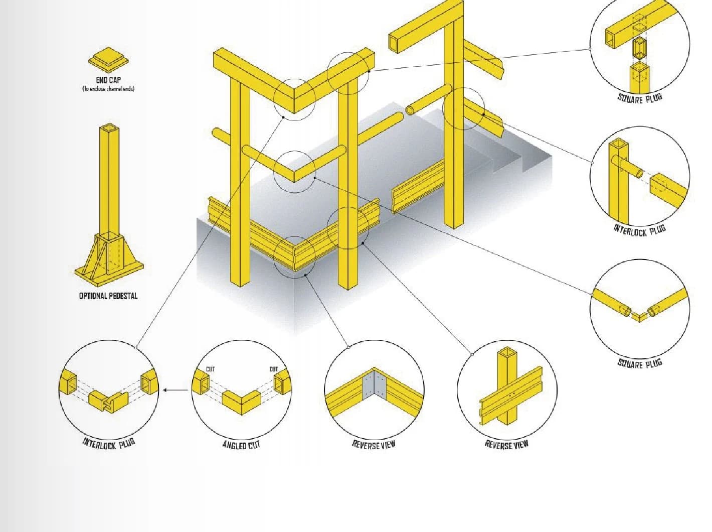
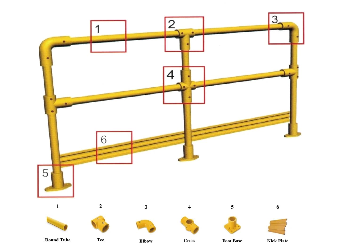
Square- and round-tube systems join differently. In F1's square-tube system, 50 × 50 × 6.4 mm top and middle rails connect through internal 38 × 38 × 6.4 mm insert splices and corner fittings, with rivets listed in the catalog. The round-tube system uses 50 mm tubes with molded elbow, tee, cross and foot-base fittings, fixed with screws. UFGS 06 82 14 describes a third arrangement: rails running unbroken through the posts, the top rail seated in a machined pocket at the top of each post, joined by a combination of bonding and riveting, with exposed corners radiused.
Whichever system is supplied, the fittings and the adhesive are part of the tested assembly. Mix the bonding kit to its ratio, use it within its working time, and respect its temperature limits. Do not load the rail, or lean on it, until the adhesive has reached the cure time in the kit's instructions. Put splices where the approved drawing shows them, and do not add splices on site to use up short lengths.
Cutting, drilling and sealing
Every cut and hole exposes glass fibers. Cut with carbide or diamond tools, drill with carbide-tipped bits, and work with dust extraction, a suitable respirator, eye protection and covered skin. UFGS 06 82 14 requires all shop and field cuts to be coated with vinyl ester resin for corrosion resistance, and drilling that leaves clean, true surfaces with no sharp or protruding edges. Use the sealing resin supplied or specified with the handrail, and deburr rivet and screw holes before the fittings go on.
Kick plates, stairs and gates
Kick plates close the gap at the walking surface. F1's catalog lists 100 × 14 × 3 mm kick plates for the square-tube system, joined with splice plates and 90° splice angles at corners, and 101 × 14 × 3 mm kick plates for the round-tube system. Where OSHA 1910.29 requires toeboards, they must be at least 3.5 in (9 cm) tall, so check the kick plate against the rule that governs the project. On stairs, rails follow the rake of the steps, within the same 1/4 in in 12 ft alignment tolerance. Openings for ladders and access points need their own protection, such as a self-closing gate or offset opening, as the drawing shows.
Storage and handling before installation
UFGS 06 82 14 asks for materials to arrive in the manufacturer's marked bundles and packages, with adhesives, resins and hardeners in clearly marked boxes, and to be stored in dry indoor facilities between 70 and 85 °F (21 and 29 °C) until needed. The temperature range matters most for the adhesives. Handle tubes and fittings so that they are not abraded, cracked, chipped or twisted, and keep them off wet ground. For outdoor service, UFGS asks for UV protection built into the profiles: UV inhibitors in the resin, a synthetic surfacing veil and a UV-resistant coating.
Final checks at handover
Walk the whole run. Check every post for plumb and every rail for line and level, look for missing rivets or screws and uncured or squeezed-out adhesive, and confirm that anchors are tightened to the drawing. Every cut end should be sealed, with no sharp edges at fittings or end caps. Kick plates and gates should be complete. UFGS 06 82 14 also asks for a signed manufacturer's certification of installation and the manufacturer's instructions for care and maintenance, which make a good handover record on any project.
To choose a system, compare the square- and round-tube options on our fiberglass handrail and guardrail systems page, and send the layout, governing standard, base substrate and exposure through it for a project review.
FRP handrail installation questions
How far apart should FRP handrail posts be?
No farther apart than the limit for the system and the governing loads. F1's catalog layouts use 1,500 mm maximum, the US DoD guide specification UFGS 06 82 14 limits posts to 72 in (1.83 m), and EN ISO 14122-3 limits stanchions to 1,500 mm for machinery access. The approved project drawing sets the spacing.
Do cut ends of fiberglass handrail need sealing?
Yes. UFGS 06 82 14 requires every shop and field cut to be coated with vinyl ester resin for corrosion resistance. Sealing keeps moisture and chemicals out of the exposed fibers. Use the resin supplied or specified by the handrail manufacturer.
How are FRP rails joined to the posts?
With the system's own fittings, bonded with the supplied adhesive and fastened with rivets, screws or bolts. UFGS 06 82 14 describes rails that run continuously through the posts and are joined by bonding and riveting. Round-tube systems use molded elbow, tee, cross and foot-base fittings for the same job.
What anchors should FRP handrail post bases use?
Corrosion-resistant anchors chosen for the substrate, edge distance and design load. UFGS 06 82 14 calls for anchors that sustain four times the design load in concrete and six times in masonry when tested to ASTM E488, with Type 316 stainless steel fasteners. Catalog anchor sizes are references; the anchor schedule belongs on the approved drawing.